

So, we're gonna build the entire radio controller using the Arduino microcontroller. We need to make the joystick and the receiver. This controller could have up to 32 8 bits channels. I will use a seacond hand radio controller. This is a walkera controller with very high quality joysticks. The most important parts of the radio controller are the joysticks, better said, the potentiometers. There are a lot of cheap radio controllers with very bad quality joysticks. The truth is that the first Arduino radio controller that I've was using joysticks like this cheap joystick modules from ebay.
In the above photo you can see the cheap radio controller used in the previous tutorial of the RC 3D printed Spitfire plane where I've also used a seacond hand radio controller but with smaller potentiometers. But in this case here I want a higher quality controller. The other one was quite good but using high quality potentiometers will give us better precision and stability of the drone flight.
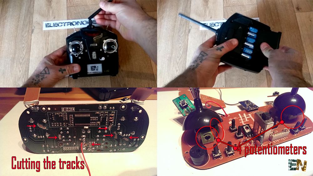
I bought this radio controller from a second hand app for just 7 euros. That's amazing. This has two high quality joysticks which give us 4 channels. It also has three extra digital channels, toggle switches.
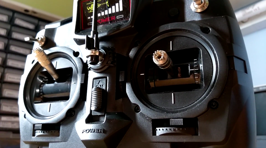
We will open this controller case with just 4 screws. Maybe remove all the electronic inside because we don't need that anymore. This is kind of an old radio controller with 35MHz crustal oscilator. This kind of controllers is beacoming less common each day because if you go to a park and there is another person using the same crystal frequency you will control his RC toy as well and you don't want that. We will build a 2.4GHz one using the NRF24 module which is an amazing small and cheap module.
All we want is to connect our Arduino inside the case to all the 4 potentiometers and maybe to the extra 3 digital toggle switches as well. Maybe we add a few more extra switches or potemtiometers to have even more channels.
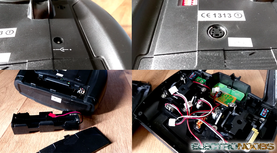
This case is great. It aleready has a 8 x 1.5V battery pack. It has an middle on/off switch, a 12V adaptor to charge the batteries, a battery level indicator, a PS/2 connecter that I could use to program the Arduino and the two high quality joysticks. This are all great features that I will use in this project.
First of all we are going to look at the power schematic. We have to supply the 12 volts from the battery to the Arduino input and the 3.3 voltage regulator. We do need this 3.3 volts voltage regulator because the NRF24 module draws too much current and Arduino can't supply that much current. So you need to buy a cheap external 3.3 volts regulator like this one. Now we conect the battery negative output to any of the GND pins of the arduino and the positive output to the on/off switch that the case already has. The other pin of the switch will go directly to the Vin pin of the Arduino and to the 3.3 voltage regulator input.
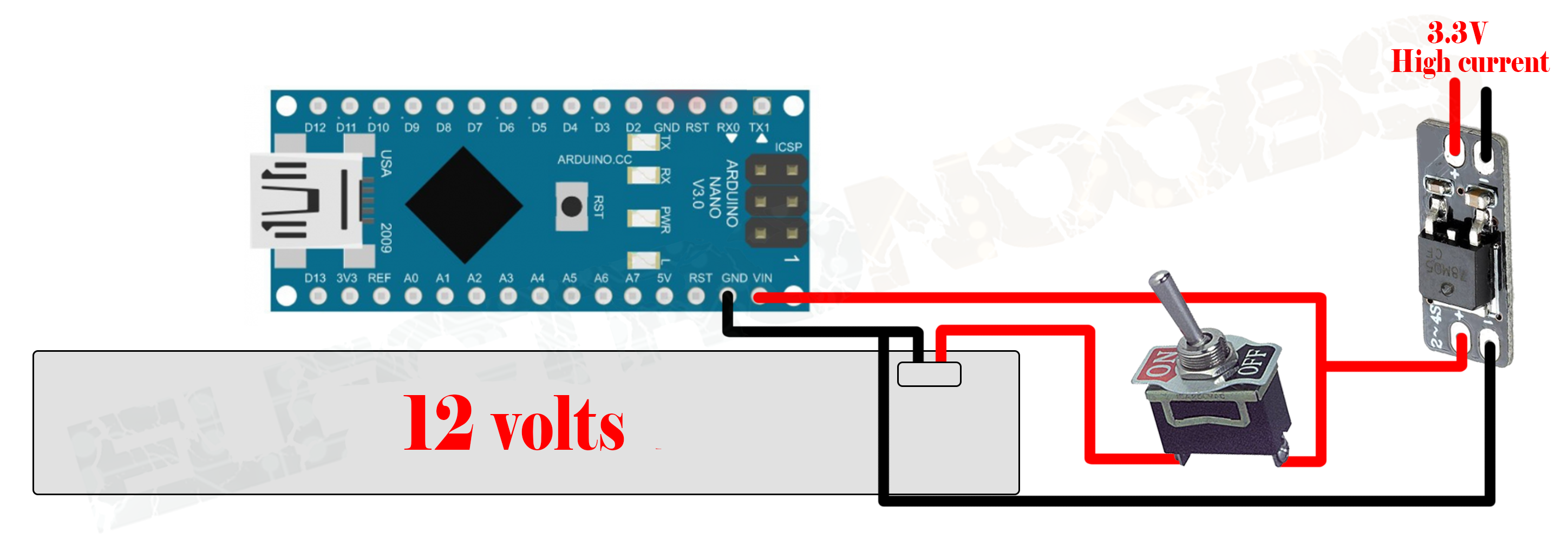
The battery could be a 3S 11.1 volts or in this case, the radio controller case already has a 8 pack of 1.5 volts batteries with a total of 12 volts. Now every time that the switch is turned on we will have 12 volts at the Arduino input and 5 volts at the voltage regulator output. Arduino NANO already has a 5 and 3.3 volts regulator on it but that won't give us the needed current.
Now is time to connect the power amplified NRF24 radio module. We need an amplified one because the transmitter always needs to radiate more power in order obtain more range. The receiver could be normal NRF24 modules. The next schematic show you how to connect each pin of the module to the Arduino.
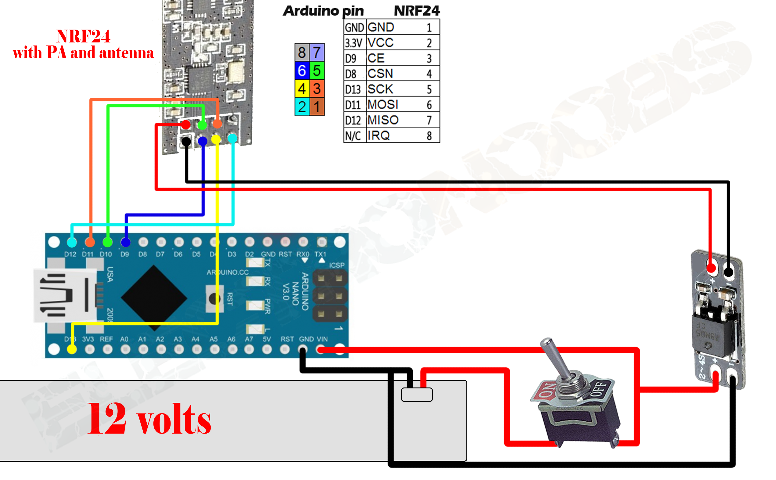
The CE and CSN pin could be any other digital pin from the Arduino because those could be changed later in the code. But all the other pins like the MISO, MOSOI and CLK must be always the same because those are the SPI comunication pins. So, supply 3.3 volts to the module and we are ready to go to the next part. In the next schematic we can see how to connect the 4 potentiometers of the radio controller to 4 analog inputs of the Arduino.
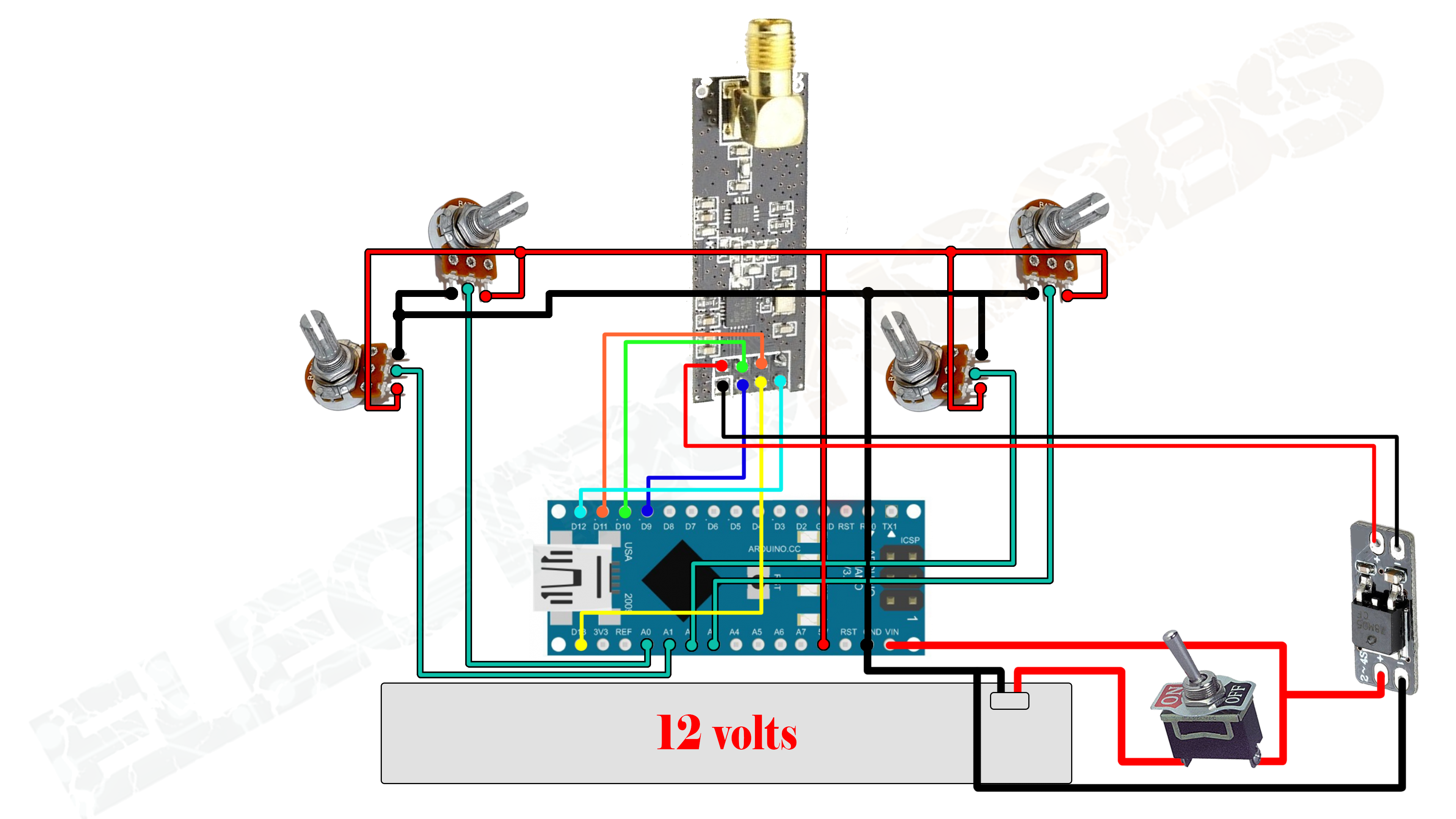
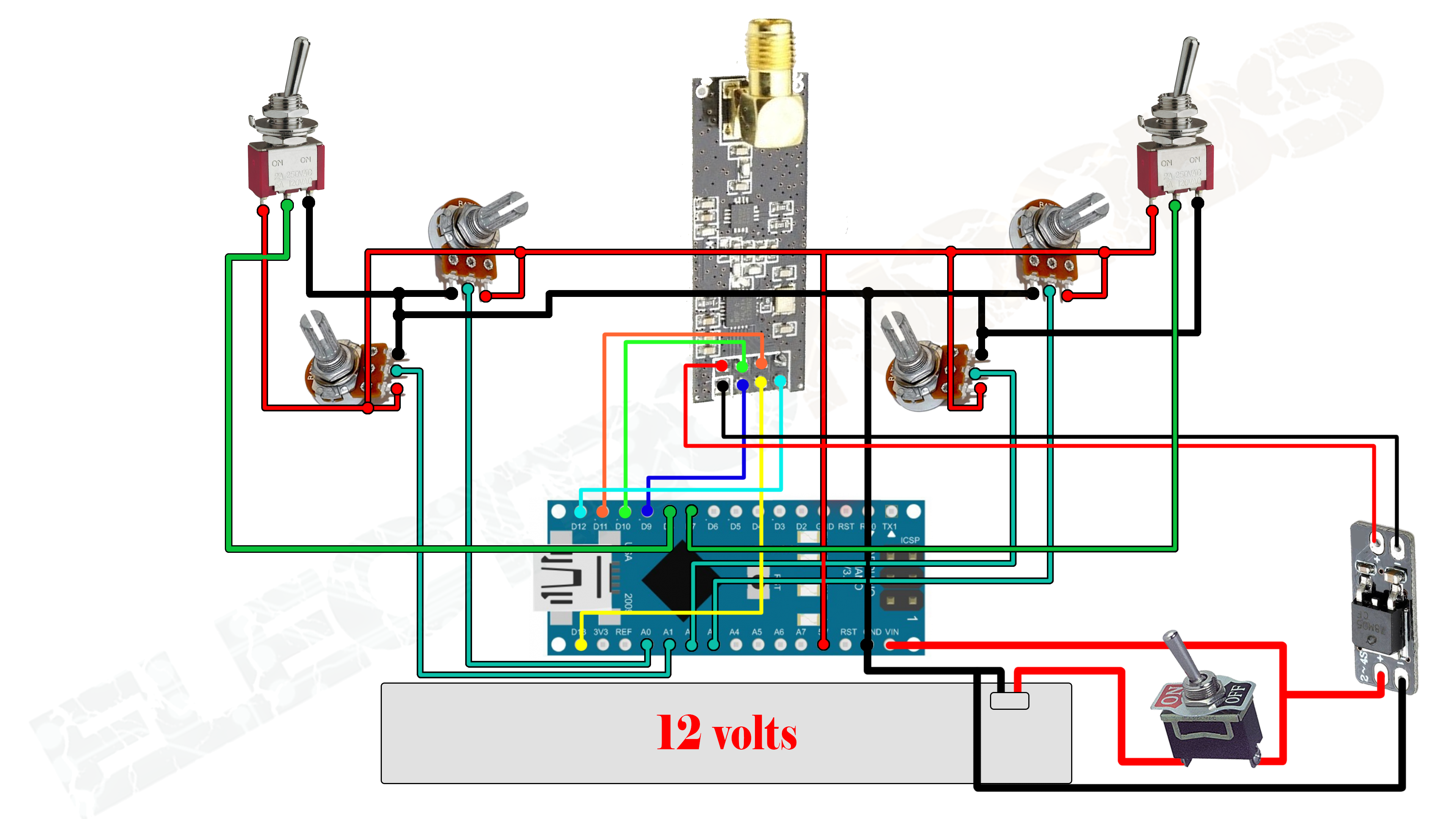
I've used analog pins A0, A1, A2 and A3 to connect each of the 4 potentiometers. First we have to supply 5 volts to the right pin of each potentiometer and ground to the left pin of each potentiometer. In this way we will have 0 volts to the analog inputs when the potentiometer is in the lowest position and 5 volts when in the highest and any value from 0 to 5 volts in between. Arduino has 10 bits ADC which will give us values from 0 to 1024 units. Now we have our joysticks connected. It's time to add the extra toggle switches channels as well. The switches are digital channels because they only have 0 and 1 values not like in the potentiometers case with values from 0 to 1024.
This sould be our final schematic for the radio transmitter. Of course we could always add an extra potentiometer to have an extra analog channel to maybe control a light on the drone or so. I'll also connect the 5 wires of the mini USB connector of the Arduino NANO to the PS/2 connector that the case aleready has on the back. Like this I¡ll program the microcontroller using that connecter. I will also connect the battery level monitor that the case has directly to the battery. The case also has a DIP switches on the back. I'll connect those too to the extra digital pins that i have on the Arduino. I'll use those switches to change the radio control channel for maybe use it with more than one receiver.
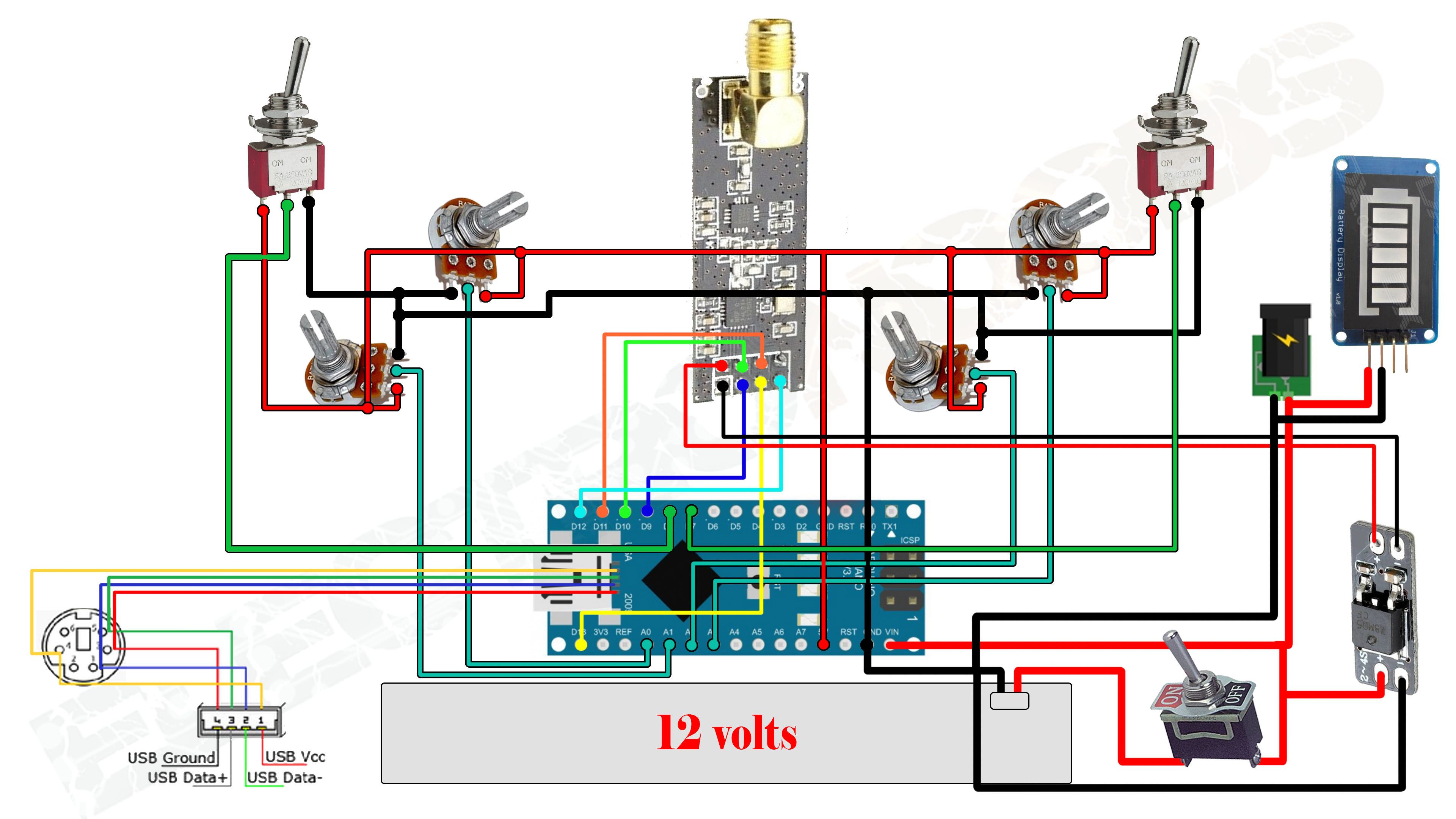
In this final schematic I've added the PS/2 connector soldered to the mini USB pins. In this way I can program it using that connecter. I also connected the 12 volts jack to charge the battery. The battery level indicator is soldered directly to the 12 volts pins. I know that this final schematic looks quite complicate but if you do it step by step like shown in the photos it would be quite easy. You don't have to mount this final part if you don't want the PS/2 connector, battery level indicator and 12 volts plug.
Copy the next transmitter code in a new sketch on your Arduino IDE. Compile and upload it to your Arduino NANO.
/*A basic 4 channel transmitter using the nRF24L01 module.*/
/* Like, share and subscribe, ELECTRONOOBS */
/* http://www.youtube/c/electronoobs */

/* First we include the libraries. Download it from
   my webpage if you donw have the NRF24 library */

#include <SPI.h>
#include <nRF24L01.h>
#include <RF24.h>

/*Create a unique pipe out. The receiver has to
  wear the same unique code*/

const uint64_t pipeOut = 0xE8E8F0F0E1LL;

RF24 radio(9, 10); // select  CSN  pin

// The sizeof this struct should not exceed 32 bytes
// This gives us up to 32 8 bits channals
struct MyData {
  byte throttle;
  byte yaw;
  byte pitch;
  byte roll;
  byte AUX1;
  byte AUX2;
};

MyData data;

void resetData()
{
  //This are the start values of each channal
  // Throttle is 0 in order to stop the motors
  //127 is the middle value of the 10ADC.

  data.throttle = 0;
  data.yaw = 127;
  data.pitch = 127;
  data.roll = 127;
  data.AUX1 = 0;
  data.AUX2 = 0;
}

void setup()
{
  //Start everything up
  radio.begin();
  radio.setAutoAck(false);
  radio.setDataRate(RF24_250KBPS);
  radio.openWritingPipe(pipeOut);
  resetData();
}

/**************************************************/

// Returns a corrected value for a joystick position that takes into account
// the values of the outer extents and the middle of the joystick range.
int mapJoystickValues(int val, int lower, int middle, int upper, bool reverse)
{
  val = constrain(val, lower, upper);
  if ( val < middle )
    val = map(val, lower, middle, 0, 128);
  else
    val = map(val, middle, upper, 128, 255);
  return ( reverse ? 255 - val : val );
}

void loop()
{
  // The calibration numbers used here should be measured
  // for your joysticks till they send the correct values.
  data.throttle = mapJoystickValues( analogRead(A0), 13, 524, 1015, true );
  data.yaw      = mapJoystickValues( analogRead(A1),  1, 505, 1020, true );
  data.pitch    = mapJoystickValues( analogRead(A2), 12, 544, 1021, true );
  data.roll     = mapJoystickValues( analogRead(A3), 34, 522, 1020, true );
  data.AUX1     = digitalRead(7);
  data.AUX2     = digitalRead(8);

  radio.write(&data, sizeof(MyData));
}
Now that you've upload the code to your transmitter is time to give it a test to see if it's working. For that, connect another arduino (UNO IN THIS CASE) on a breadboard to another NRF24 module using the same pins as in the transmitter schematic. Use arduino UNO because it has a decent current on the 3.3 volts output and it's perfect for this test. Now upload this next receiver test code to it and open the serial monitor. Power up the transmitter and observe the values on the serial monitor. You should see the 6 channals values printed on the serial monitor. If not, something is wrong and you should check all the connections.
/* Test code for the Radio control transmitter
 *  Install the NRF24 library to your IDE
 * Upload this code to the Arduino UNO
 * Connect a NRF24 module to it:

    Module // Arduino UNO

    GND    ->   GND
    Vcc    ->   3.3V
    CE     ->   D9
    CSN    ->   D10
    CLK    ->   D13
    MOSI   ->   D11
    MISO   ->   D12

This code should print the received values to the serial monitor
Please, like share and subscribe : https://www.youtube.com/c/ELECTRONOOBS
*/

#include <SPI.h>
#include <nRF24L01.h>
#include <RF24.h>
const uint64_t pipeIn = 0xE8E8F0F0E1LL; //Remember that this code is the same as in the transmitter

RF24 radio(9, 10);

//We could use up to 32 channels
struct MyData {
byte throttle; //We define each byte of data input, in this case just 6 channels
byte yaw;
byte pitch;
byte roll;
byte AUX1;
byte AUX2;
};

MyData data;

void resetData()
{
//We define the inicial value of each data input
//3 potenciometers will be in the middle position so 127 is the middle from 254
data.throttle = 0;
data.yaw = 127;
data.pitch = 127;
data.roll = 127;
data.AUX1 = 0;
data.AUX2 = 0;

}

/**************************************************/

void setup()
{
Serial.begin(250000); //Set the speed to 9600 bauds if you want.
//You should always have the same speed selected in the serial monitor
resetData();
radio.begin();
radio.setAutoAck(false);
radio.setDataRate(RF24_250KBPS);

radio.openReadingPipe(1,pipeIn);
//we start the radio comunication
radio.startListening();

}

/**************************************************/

unsigned long lastRecvTime = 0;

void recvData()
{
while ( radio.available() ) {
radio.read(&data, sizeof(MyData));
lastRecvTime = millis(); //here we receive the data
}
}

/**************************************************/

void loop()
{
recvData();
unsigned long now = millis();
//Here we check if we've lost signal, if we did we reset the values
if ( now - lastRecvTime > 1000 ) {
// Signal lost?
resetData();
}

Serial.print("Throttle: "); Serial.print(data.throttle);  Serial.print("    ");
Serial.print("Yaw: ");      Serial.print(data.yaw);       Serial.print("    ");
Serial.print("Pitch: ");    Serial.print(data.pitch);     Serial.print("    ");
Serial.print("Roll: ");     Serial.print(data.roll);      Serial.print("    ");
Serial.print("Aux1: ");     Serial.print(data.AUX1);      Serial.print("    ");
Serial.print("Aux2: ");     Serial.print(data.AUX2);      Serial.print("\n");


}

/**************************************************/
I hope that the transmitter works OK, Is now time to make the receiver box for this transmitter. It will also have a NRF24 module but this time it could be a small one without antenna. It will receive the 6 channals signals and output 6 PWM signals for each channal. It could also output a PPM sum signal with all the 6 channals. There will be a different code for each part. Let's go!
So, any transmitter needs a receiver in order to work. We want the same values of the analog read of each potentiometer to be received on our drone. Usually a radio reciver gives out a PWM or PPM signal. In the past tutorial of the RC plane, the receiver worked with PPM signal. In the next part of the tutorial we will see how to create both types of receivers, PPM and PWM. Personally I recommend the PPM signal. PPM is more constant. Using the arduino timers we can easy create a PPM signal for out 6 channels using just one pin of the arduino. If we want to have a PWM signal for each channel we would have to use a pin for each on of them. Arduino NANO has 6 PWM pins and we use 2 of those for the NRF moduel, pin D10 and D11. We also use D9 but the CS pin can be any other. So, inn order to have 6 different PWM signals we have to use tiumers and count the dime for each pulse lenght. I've made some tests and the PWM signal has a small wobble at the fall edge. That's due to more or less time used for the radio comunication. I have also used interuption for everythig but there still is a small wobble.
That's why I recommend the PPM part fot this tutorial.