


The flight controller is the nerve center of a drone. Drone flight control systems are many and varied. From GPS enabled autopilot systems flown via two way telemetry links to basic stabilization systems using hobby grade radio control hardware, there is an open source project for you.
Modern drone flight controllers can trace their roots back to R/C helicopters. Historically, R/C planes were controlled directly by the pilot’s radio. Helicopters added a new wrinkle to the mix: tail rotors. Helicopters use their tail (or anti-torque) rotor to counteract the torque of the main rotor attempting to spin the entire helicopter’s body. It all works great when the helicopter is hovering, but what about when the pilot throttles up to fly out? As the pilot throttles up, the torque increases, which causes the entire helicopter to do a pirouette or two, until the torque levels out again. The effect has caused more than one beginner pilot to come nose to nose with their R/C heli.
The solution to this problem was gyroscopes, heavy brass spinning weights that tilted in response to the helicopter’s motion. A hall effect sensor would detect that tilt and command the tail rotor to counteract the helicopter’s rotation. As the years wore on, mechanical gyros were replaced by solid state MEMS gyros. Microcontrollers entered the picture and brought with them advanced processing techniques. Heading hold gyros were then introduced. Whereas older “rate only” gyros would drift, weathervane, and wiggle, heading hold gyros would lock down the helicopter’s nose until the pilot commanded a turn. These single axis flight controllers were quickly adopted by the R/C helicopter community.
Today’s flight control systems have many sensors available to them – GPS, barometric pressure sensors, airspeed sensors, the list goes on. The major contributors to the flight calculations are still the gyros, coupled with accelerometers. As the name implies, accelerometers measure acceleration – be it due to gravity, a high G turn, or stopping force. Accelerometers aren’t enough though – An accelerometer in free fall will measure 0 G’s. Turning forces will confuse a system trying to operate solely on accelerometer data. That’s where gyros come in. Gyros measure rate of rotation about an axis. Just as our helicopter example above covered yaw, gyros can be used to measure pitch and roll of an aircraft. A great comparison of gyros and accelerometers is presented in this video from InvenSense.
We will use the MPU6050 gyro and accelerometer module. It has a i2c comunication and that's awsome becasue it only needs 2 pins from the arduino, clock and data. Also you can connect multiple i2c modules to the same port. SO if you are thinking on adding some more measurement modules like a barometer or magnetometer.
So why do we need a gyro?
Well the drone won't stay streight by itself and flying it without a flight controller would be impossible. A gyro modules will detect any movement on each of the 3 axis. Usually it gives back rotation/second values to the microcontroller. Using those values we could calculate the angle of the drone in each moment. If we know the angle we can always give different power to the motors in order to stabilize and counter the unwanted forces.
Before we look at the flight controller schematic let's first understand what type of drone we are going to build. We will build a quad-x shaped drone, which means that it will have 4 motors placed in a cruce shape. For that we have to define the front of the plane. We will have two motors on the front side and two on the back side as we can see in the figure below.
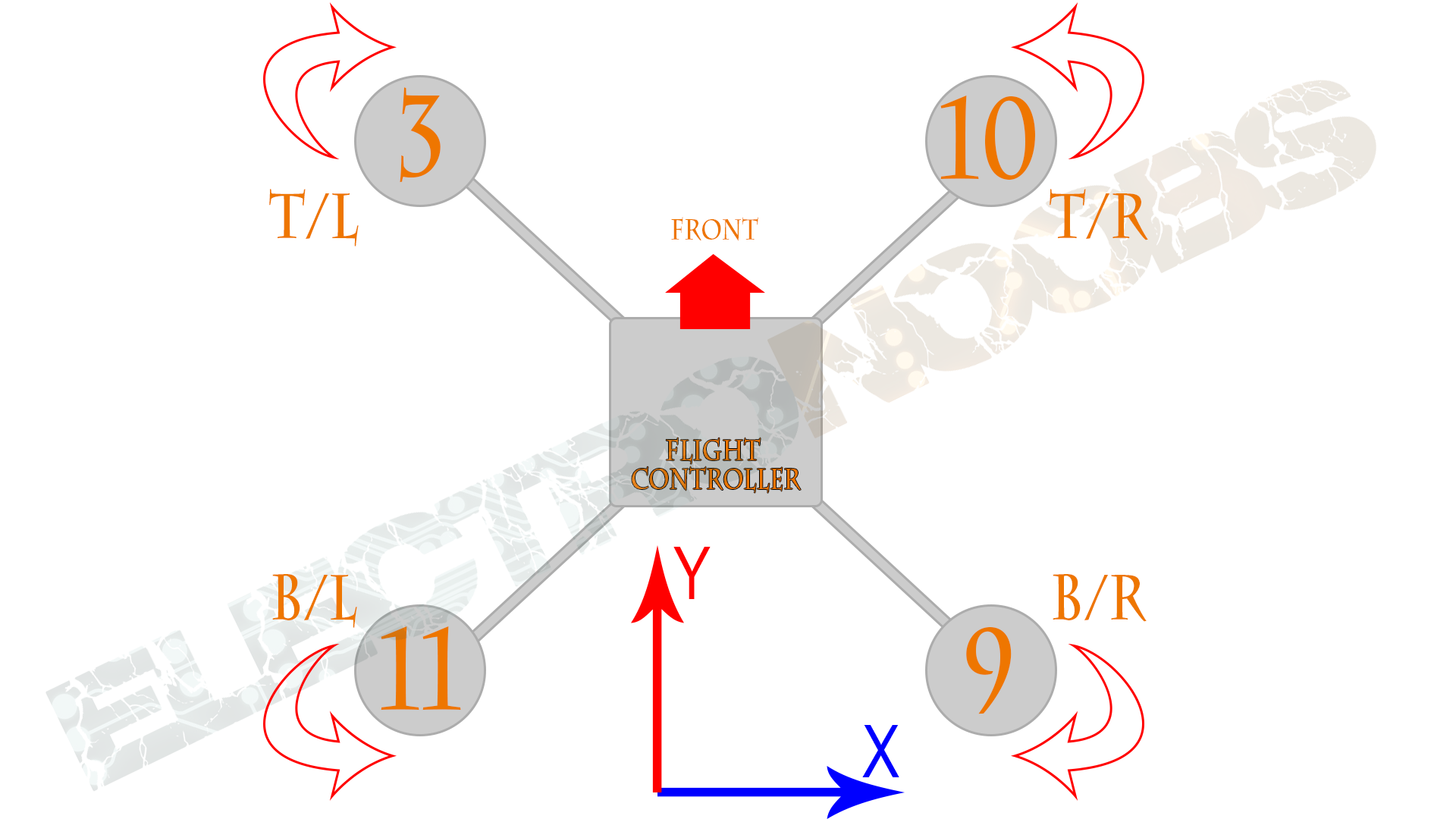
Now that we defined the front of our drone we can set the axis of it. From left to right will be the "X" axis and top to bottom the "Y" axis. We have to place the flight controller as centered it can. It will detect fast movement of the drone and adjust the PWM signal for each of the four motors in order to stabilize the drone.
We can see that each motor has a number. That number coresponds to the digital pin of the arduino. Each motor has one signal pin for thes ESCs. We can also see that each motor spins in a different way in order to create a specia air vortex. Both back and front pair sof motors spin tward the interior of the drone. We've talk about this in the body constructuction.
So now we ckow that the flight controller needs 4 output pins for each motor and a IMU (inertial movement unit) connected to it. It also needs input from each of the 6 channels of the radio receiver.
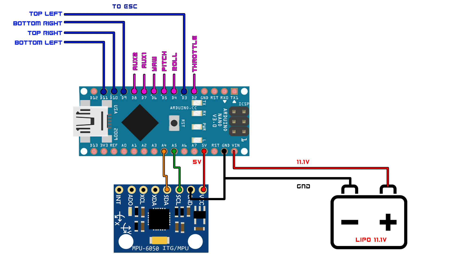
With this configuration our drone would be able to fly without problems. We can add more modules like a magnetometer or a barometer but with gyro and accelerometer it's just fine for now. So once again we use the lipo battery of the drone to supply the flight controller. Connect both ground and the 11.V directly to the Vin pin. The arduino NANO already has 5 and 3.3 voltage regulators. We connect pins D3, D9, D10 and D11 to each of the four motors ESCs. Each esc also needs to share ground with the arduino in order to understand the pwm signals.
Supply 5 volts to the MPU6050 module and ground as well. Connect the SDA (A4) and SCL (A5) pins to the arduino analog pins A4 and A5 and we are done.

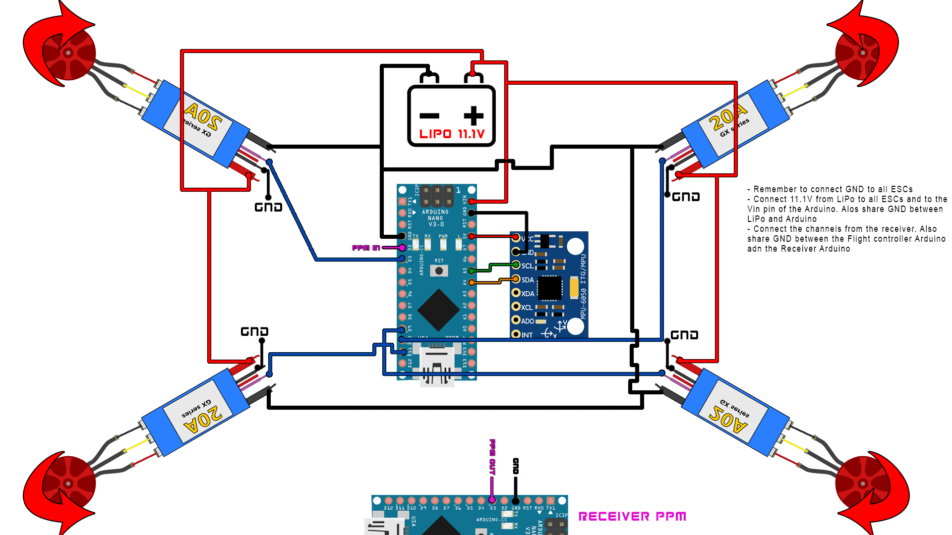
This is sort of a full schematic of the flight controller. We can se the receiver with the 6 channels, the 4 ESCs adn brushless motors. Everything has to share the same ground. Supply 11.1 volts to each ESC and to the flight controller Arduino. Connect the i2c MPU6050 module and place it in the middle of the drone.
It's now time to upload the code of the flight controller.
To program our code we have two options. One is to create the entire code for the Arduino and create a PID control with the data from the IMU and the receiver and control the drone. The other option is to use an already tested code. In this part we will use the second option. The platform that we will use is called Multiwii. Multiwii is a flight control platform that could adapt for a big variety of flying machines. Drones, planes, helicopters and so on. The flight controller should read the accelerations and gyro data from the MPU uint. Next it should calculate the real angle of the drone and using a PID operation control the 4 motors and move the drone in the desired direction. Ok so download the multiwii zip file from a link below.
Unzip the file. Inside of the unzipped folder you will find the Arduino code that we should upload to the flight controller board and also a Java/Procesing platform for live configuration of the board. Open the Arduino IDE. Now go to the folder and open the .ino file. This will open a bunch of libraries. Go to the config.h library. Here is where we will make the configuration of our drone. We don’t have to change anything in the other libraries. First let’s scroll down to the type of multicopter.

To activate any configuration you should only delete the double slash line that comments that part of the code. The type of the drone that I’m building is a quad X with 4 motors positioned in a shape of an X. Now let’s scroll down a little bit more.
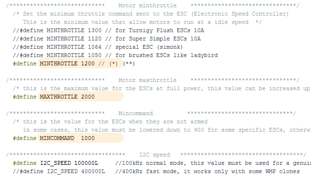
Here we define the minimum throttle. To control the motors, we have to send a PWM signal to the esc. The PWM is modulated by changing the pulse width of the signal. This width is measured in micro seconds. The motors that I’m using have a throttle range from 1000 us to 2000us where 1000 is no speed at all and 2000 is full throttle. I like to live my drone on 1150 or 1200 minimum throttle because that will ensure me that I’ll have no motors delay when I start flying my drone. That would also mean that the motors will spin at low RPM while in the stand by mode. Ok I live the maximum throttle at 2000. The minimum command is the minimum range that the radio controller could send. In this case, it will be 1000 us. We will se this when we will build the radio controller. Now scroll down to the IMU boards.
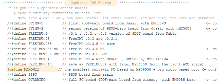
I’ll uncomment one that has the MPU 60 50 module. I select the NANOwii board since this one is for Arduino anno with a MPU6050 board. The next step is to establish a PPM communication between the radio controller receiver and the flight controller. The receiver that we will build will send an 8 channel PPM signal with the values for the throttle, yaw, pitch and roll. For that type control F to open the find tab. Now type PPM and click search.
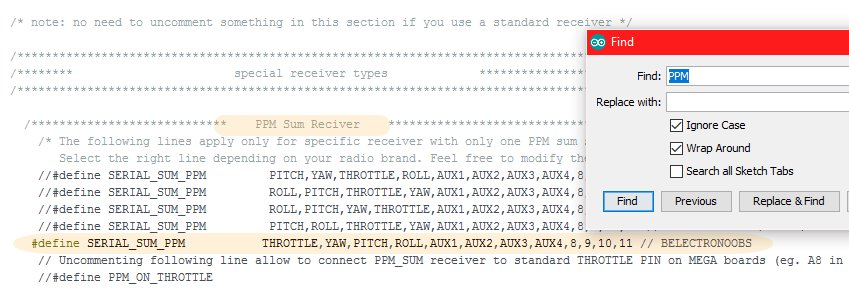
This is the order of the PPM channels that we will receive. Now save and compile the code. Connect the Arduino of the flight controller to an USB and upload the code. Our flight controller is ready. Now to test it open the Java application from the other folder. Keep the Arduino connected to the USB and select the corresponding com. Click start and move the flight controller around.
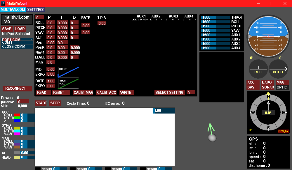
As you can see we have a decent live control of the board. You could edit the PID values, calibrate the sensor or change the commands.