 About me
  History
  Let's learn
  Contact us
  Arduino tutorials
 Circuits tutorials
  Robotics tutorials
 Q&A
Q&A Blog
Blog  Arduino
  Circuits
 Robotics
  Modules
  Gadgets
  Printers
  Materials
  3D objects
  3D edit
  Donate
  Reviews
  Advertising


32 channels Arduino radio controller

 Drone body
 Radio control
 Flight control
Receiver
Some info...
Crystal-controlled superheterodyne receivers with better selectivity and stability made control equipment more capable and at lower cost. Multi-channel developments were of particular use to aircraft, which really needed a minimum of three control dimensions (yaw, pitch and motor speed), as opposed to boats, which required only two or one.
As the electronics revolution took off, single-signal channel circuit design became redundant, and instead radios provided proportionally coded signal streams which a servomechanism could interpret, using pulse-position modulation (PPM). More recently, high-end hobby systems using Pulse-code modulation (PCM) features have come on the market that provide a computerized digital bit-stream signal to the receiving device, instead of the earlier PPM encoding type. However, even with this coding, loss of transmission during flight has become more common[citation needed], in part because of the ever more wireless society. Some more modern FM-signal receivers that still use "PPM" encoding instead can, thanks to the use of more advanced computer chips in them, be made to lock onto and use the individual signal characteristics of a particular PPM-type RC transmitter's emissions alone, without needing a special "code" transmitted along with the control information as PCM encoding has always required.
Schematic
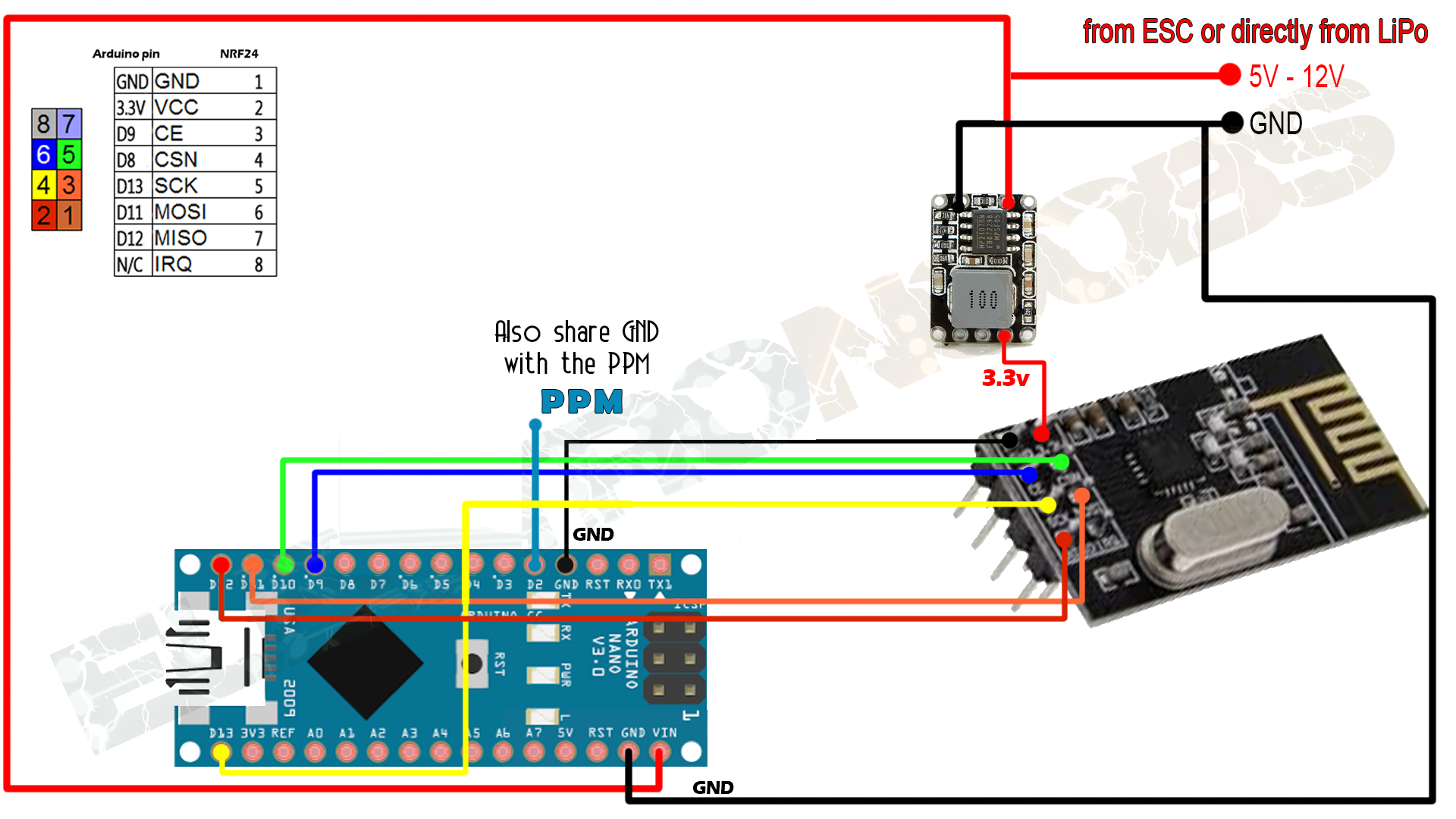
So, we will use the same NRF24 radio module to receive the signal. This modules work both as transmitter or receiver and they could also do it both at same time. For only 2 euros this are some awsome modules and I use them always. The connections from the Arduino to the receiver are the same. We can see those connection in the schematic below. We will have two parts. One for a PWM output and other for PPM.
A.0 PWM receiver
Let's start with the PWM receiver. We will use 6 pins from the microcontroller to create our PWM signals. In case of the two auxiliary channels those signals will be digitals, high or low.
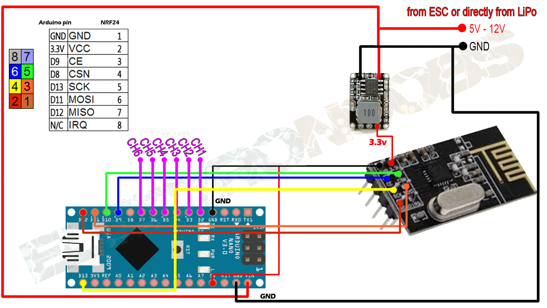
So, as we can see in the schematic above the connections to the radio module are the same as in the transmitter case. You can se that now we are using a module without power amplifier or antenna. That's because you don't need to amplify anything to receive signal. If the signal is strong enough to reach you that's it.
Now, we will use pin D2,D3, D4, D5, D6, and D7 for our pwm output channelsbecause this pins are from the same port register. D6 and D7 will be the two digital auxiliary channels. Try to solder the module as close to the Arduino and use short wires to avoid interferencies and to be able to fit it inside a case. I will 3D design and print a case for this one.
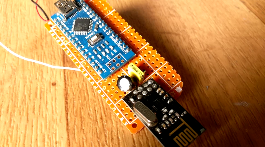
I've use an SMD voltage regulator soldered directly on the drilled PCB. It is an AMS1117 3.3 voltage regulator and it is soldered on the back. You can see the capacitors used for the regulating circuit between the arduino and the module.
A.1 Case and outputs
As you can see in the photos above we haven't soldered the output pins for the 6 channels or the PPM pin. First I had to design the case in order to knew where to place the pins. At the same time that I was designing it I decided where it was better to put the pins. Normal radio control receivers have rows of 3 pins for each channel. One is ground, the other is 5 volts supply and the last is the signal pin. I will do the same with mine in order to have the same type of receiver as a comercial one.

A.3 Code - PWM (with servo.writeMicroseconds)
Copy the next PWM receiver in a new sketch on your Arduino IDE. Compile and upload it to your Arduino NANO.
You can download the
To install it we just go to Sketch -> Include library and we open the .zip file that we've just downloaded.
/* Receiver code for the Arduino Radio control with PWM output
 *
 *  THIS ONLY WORKS WITH ATMEGA328p registers!!!!
 *  It gives a nice PWM output on pins D2, D3, D4, D5, D6 and D7. Still working on it...
 *
 *  Install the NRF24 library to your IDE
 *  Import the servo library as well
 * Upload this code to the Arduino UNO
 * Connect a NRF24 module to it:

    Module // Arduino UNO

    GND    ->   GND
    Vcc    ->   3.3V
    CE     ->   D9
    CSN    ->   D10
    CLK    ->   D13
    MOSI   ->   D11
    MISO   ->   D12

This code receive 6 channels and create a PWM output for each one on D2, D3, D4, D5, D6 and D7
Please, like share and subscribe : https://www.youtube.com/c/ELECTRONOOBS
*/

#include <SPI.h>
#include <nRF24L01.h>
#include <RF24.h>
#include <Servo.h>

//Define widths
int pwm_width_2 = 0;
int pwm_width_3 = 0;
int pwm_width_4 = 0;
int pwm_width_5 = 0;
int pwm_width_6 = 0;
int pwm_width_7 = 0;

Servo PWM2;
Servo PWM3;
Servo PWM4;
Servo PWM5;
Servo PWM6;
Servo PWM7;

                    //We could use up to 32 channels
struct MyData {
byte throttle;      //We define each byte of data input, in this case just 6 channels
byte yaw;
byte pitch;
byte roll;
byte AUX1;
byte AUX2;
};
MyData data;


const uint64_t pipeIn = 0xE8E8F0F0E1LL;     //Remember that this code is the same as in the transmitter
RF24 radio(9, 10);


void resetData()
{
//We define the inicial value of each data input
//3 potenciometers will be in the middle position so 127 is the middle from 254
data.throttle = 0;
data.yaw = 127;
data.pitch = 127;
data.roll = 127;
data.AUX1 = 0;
data.AUX2 = 0;
}

/**************************************************/

void setup()
{
  //Set the pins for each PWM signal
  PWM2.attach(2);
  PWM3.attach(3);
  PWM4.attach(4);
  PWM5.attach(5);
  PWM6.attach(6);
  PWM7.attach(7);

  //Configure the NRF24 module
  resetData();
  radio.begin();
  radio.setAutoAck(false);
  radio.setDataRate(RF24_250KBPS);
  radio.openReadingPipe(1,pipeIn);

  //we start the radio comunication
  radio.startListening();
}

/**************************************************/

unsigned long lastRecvTime = 0;

void recvData()
{
while ( radio.available() ) {
radio.read(&data, sizeof(MyData));
lastRecvTime = millis(); //here we receive the data
}
}

/**************************************************/

void loop()
{
recvData();
unsigned long now = millis();
//Here we check if we've lost signal, if we did we reset the values
if ( now - lastRecvTime > 1000 ) {
// Signal lost?
resetData();
}

pwm_width_2 = map(data.throttle, 0, 255, 1000, 2000);     //PWM value on digital pin D2
pwm_width_3 = map(data.yaw,      0, 255, 1000, 2000);     //PWM value on digital pin D3
pwm_width_4 = map(data.pitch,    0, 255, 1000, 2000);     //PWM value on digital pin D4
pwm_width_5 = map(data.roll,     0, 255, 1000, 2000);     //PWM value on digital pin D5
pwm_width_6 = map(data.AUX1,     0, 255, 1000, 2000);     //PWM value on digital pin D6
pwm_width_7 = map(data.AUX2,     0, 255, 1000, 2000);     //PWM value on digital pin D7


//Now we write the PWM signal using the servo function
PWM2.writeMicroseconds(pwm_width_2);
PWM3.writeMicroseconds(pwm_width_3);
PWM4.writeMicroseconds(pwm_width_4);
PWM5.writeMicroseconds(pwm_width_5);
PWM6.writeMicroseconds(pwm_width_6);
PWM7.writeMicroseconds(pwm_width_7);


}//Loop end
/**************************************************/
A.4 Code - PWM (interruptions)
Copy the next PWM receiver in a new sketch on your Arduino IDE. Compile and upload it to your Arduino NANO.
You can download the
To install it we just go to Sketch -> Include library and we open the .zip file that we've just downloaded.
/* Receiver code for the Arduino Radio control with PWM output
 *
 *  THIS ONLY WORKS WITH ATMEGA328p registers!!!!
 *  It gives a shifty PWM due to radio receive without interuption. Still working on it
 *
 *  Install the NRF24 library to your IDE
 * Upload this code to the Arduino UNO
 * Connect a NRF24 module to it:

    Module // Arduino UNO

    GND    ->   GND
    Vcc    ->   3.3V
    CE     ->   D9
    CSN    ->   D10
    CLK    ->   D13
    MOSI   ->   D11
    MISO   ->   D12

This code receive 6 channels and create a PWM output for each one on D2, D3, D4, D5, D6 and D7
Please, like share and subscribe : https://www.youtube.com/c/ELECTRONOOBS
*/

//Define widths
int pwm_width_2 = 0;
int pwm_width_3 = 0;
int pwm_width_4 = 0;
int pwm_width_5 = 0;
int pwm_width_6 = 0;
int pwm_width_7 = 0;


float frequency = 62.5;                     // PWM frequency in hertz
float PWM_period = ((1/frequency)*1000000);   //period in us
unsigned long previousMillis = 0;                            //Set initial timer value used for the PWM signal

#include <SPI.h>
#include <nRF24L01.h>
#include <RF24.h>

const uint64_t pipeIn = 0xE8E8F0F0E1LL;     //Remember that this code is the same as in the transmitter

RF24 radio(9, 10);

                    //We could use up to 32 channels
struct MyData {
byte throttle;      //We define each byte of data input, in this case just 6 channels
byte yaw;
byte pitch;
byte roll;
byte AUX1;
byte AUX2;
};

MyData data;

void resetData()
{
//We define the inicial value of each data input
//3 potenciometers will be in the middle position so 127 is the middle from 254
data.throttle = 0;
data.yaw = 127;
data.pitch = 127;
data.roll = 127;
data.AUX1 = 0;
data.AUX2 = 0;

}

/**************************************************/

void setup()
{
  //Set the timer

  cli();
  TCCR1A = 0; // set entire TCCR1 register to 0
  TCCR1B = 0;

  OCR1A = 100;  // compare match register (not very important, sets the timeout for the first interrupt)
  TCCR1B |= (1 << WGM12);  // turn on CTC mode
  TCCR1B |= (1 << CS11);  // 8 prescaler: 0,5 microseconds at 16mhz
  TIMSK1 |= (1 << OCIE1A); // enable timer compare interrupt
  sei();


// Register valeus: D7:D6:D5:D4:D3:D2:D1:D0
DDRD |= B11111100;  // Sets D2, D3, D4, D5, D6 and D7 as input

resetData();
radio.begin();
radio.setAutoAck(false);
radio.setDataRate(RF24_250KBPS);

radio.openReadingPipe(1,pipeIn);
//we start the radio comunication
radio.startListening();

}

/**************************************************/

unsigned long lastRecvTime = 0;

void recvData()
{
while ( radio.available() ) {
radio.read(&data, sizeof(MyData));
lastRecvTime = millis(); //here we receive the data
}
}

/**************************************************/

void loop()
{
recvData();
unsigned long now = millis();
//Here we check if we've lost signal, if we did we reset the values
if ( now - lastRecvTime > 1000 ) {
// Signal lost?
resetData();
}

pwm_width_2 = map(data.throttle, 0, 255, 1000, 2000);     //PWM value on digital pin D3
pwm_width_3 = map(data.yaw,      0, 255, 1000, 2000);     //PWM value on digital pin D4
pwm_width_4 = map(data.pitch,    0, 255, 1000, 2000);     //PWM value on digital pin D5
pwm_width_5 = map(data.roll,     0, 255, 1000, 2000);     //PWM value on digital pin D6
pwm_width_6 = map(data.AUX1,     0, 255, 1000, 2000);     //PWM value on digital pin D6
pwm_width_7 = map(data.AUX2,     0, 255, 1000, 2000);     //PWM value on digital pin D6
}//Loop end
/**************************************************/


//Timer interrupt
ISR(TIMER1_COMPA_vect){
  unsigned long currentMillis = micros();
//////////////////////PWM signal/////////////////////////
if(currentMillis - previousMillis < PWM_period) //we need a 16ms period of the signal.
 {

  ////Pin D2-Throttle////
  if(currentMillis - previousMillis < pwm_width_2)
  {
    PORTD |= B00000100;    // Sets to HIGH D2.
  }

  if(currentMillis - previousMillis > pwm_width_2)
  {
    PORTD &= B11111011;    // Sets to LOW D2.
  }

  ////Pin D3-Yaw////
  if(currentMillis - previousMillis < pwm_width_3)
  {
    PORTD |= B00001000;    // Sets to HIGH D3.
  }

  if(currentMillis - previousMillis > pwm_width_3)
  {
    PORTD &= B11110111;    // Sets to LOW D3.
  }

  ////Pin D4-Pitch////
  if(currentMillis - previousMillis < pwm_width_4)
  {
    PORTD |= B00010000;    // Sets to HIGH D4.
  }

  if(currentMillis - previousMillis > pwm_width_4)
  {
    PORTD &= B11101111;    // Sets to LOW D4.
  }

  ////Pin D5-Roll////
  if(currentMillis - previousMillis < pwm_width_5)
  {
    PORTD |= B00100000;    // Sets to HIGH D5.
  }

  if(currentMillis - previousMillis > pwm_width_5)
  {
    PORTD &= B11011111;    // Sets to LOW D5.
  }

  ////Pin D6-Aux1////
  if(currentMillis - previousMillis < pwm_width_6)
  {
    PORTD |= B01000000;    // Sets to HIGH D6.
  }

  if(currentMillis - previousMillis > pwm_width_6)
  {
    PORTD &= B10111111;    // Sets to LOW D6.
  }

 ////Pin D7-Aux2////
  if(currentMillis - previousMillis < pwm_width_7)
  {
    PORTD |= B10000000;    // Sets to HIGH D7.
  }

  if(currentMillis - previousMillis > pwm_width_7)
  {
    PORTD &= B01111111;    // Sets to LOW D7.
  }
 } //ends the if (currentMillis - previousMillis < PWM_period)


 if(currentMillis - previousMillis > PWM_period) //We reach 16ms and reset the timer
  {
   previousMillis += PWM_period;
  }
}
B.0 Part 3: Code - PPM
The schematic for the PPM type of receivger is the same as before. The only thing that changes is the PPM pin. We wont use 6 pins any more, just one. Digital pin 2 in this case. So make the connections and upload the next code to the arduino. This schematic will give a 6 channel PPM signal on pin D2 with the received information for each cahnnel.
Copy the next receiver in a new sketch on your Arduino IDE. Compile and upload it to your Arduino NANO.
You can download the
To install it we just go to Sketch -> Include library and we open the .zip file that we've just downloaded.
You can download the
/*
 * Check:  http://www.electronoobs.com/eng_robotica_tut5_2_1.php
 *
 *
A basic receiver test for the nRF24L01 module to receive 6 channels send a ppm sum
with all of them on digital pin D2.
Install NRF24 library before you compile
Please, like, share and subscribe on my https://www.youtube.com/c/ELECTRONOOBS
 */

#include <SPI.h>
#include <nRF24L01.h>
#include <RF24.h>

////////////////////// PPM CONFIGURATION//////////////////////////
#define channel_number 6  //set the number of channels
#define sigPin 2  //set PPM signal output pin on the arduino
#define PPM_FrLen 27000  //set the PPM frame length in microseconds (1ms = 1000µs)
#define PPM_PulseLen 400  //set the pulse length
//////////////////////////////////////////////////////////////////

int ppm[channel_number];

const uint64_t pipeIn =  0xE8E8F0F0E1LL;

RF24 radio(9, 10);

// The sizeof this struct should not exceed 32 bytes
struct MyData {
  byte throttle;
  byte yaw;
  byte pitch;
  byte roll;
  byte AUX1;
  byte AUX2;
};

MyData data;

void resetData()
{
  // 'safe' values to use when no radio input is detected
  data.throttle = 0;
  data.yaw = 127;
  data.pitch = 127;
  data.roll = 127;
  data.AUX1 = 0;
  data.AUX2= 0;

  setPPMValuesFromData();
}

void setPPMValuesFromData()
{
  ppm[0] = map(data.throttle, 0, 255, 1000, 2000);
  ppm[1] = map(data.yaw,      0, 255, 1000, 2000);
  ppm[2] = map(data.pitch,    0, 255, 1000, 2000);
  ppm[3] = map(data.roll,     0, 255, 1000, 2000);
  ppm[4] = map(data.AUX1,     0, 1, 1000, 2000);
  ppm[5] = map(data.AUX2,     0, 1, 1000, 2000);
  }

/**************************************************/

void setupPPM() {
  pinMode(sigPin, OUTPUT);
  digitalWrite(sigPin, 0);  //set the PPM signal pin to the default state (off)

  cli();
  TCCR1A = 0; // set entire TCCR1 register to 0
  TCCR1B = 0;

  OCR1A = 100;  // compare match register (not very important, sets the timeout for the first interrupt)
  TCCR1B |= (1 << WGM12);  // turn on CTC mode
  TCCR1B |= (1 << CS11);  // 8 prescaler: 0,5 microseconds at 16mhz
  TIMSK1 |= (1 << OCIE1A); // enable timer compare interrupt
  sei();
}

void setup()
{
  resetData();
  setupPPM();

  // Set up radio module
  radio.begin();
  radio.setDataRate(RF24_250KBPS); // Both endpoints must have this set the same
  radio.setAutoAck(false);

  radio.openReadingPipe(1,pipeIn);
  radio.startListening();
}

/**************************************************/

unsigned long lastRecvTime = 0;

void recvData()
{
  while ( radio.available() ) {
    radio.read(&data, sizeof(MyData));
    lastRecvTime = millis();
  }
}

/**************************************************/

void loop()
{
  recvData();

  unsigned long now = millis();
  if ( now - lastRecvTime > 1000 ) {
    // signal lost?
    resetData();
  }

  setPPMValuesFromData();
}

/**************************************************/

#error Delete this line befor you cahnge the value (clockMultiplier) below
#define clockMultiplier 2 // set this to 2 if you are using a 16MHz arduino, leave as 1 for an 8MHz arduino

ISR(TIMER1_COMPA_vect){
  static boolean state = true;

  TCNT1 = 0;

  if ( state ) {
    //end pulse
    PORTD = PORTD & ~B00000100; // turn pin 2 off. Could also use: digitalWrite(sigPin,0)
    OCR1A = PPM_PulseLen * clockMultiplier;
    state = false;
  }
  else {
    //start pulse
    static byte cur_chan_numb;
    static unsigned int calc_rest;

    PORTD = PORTD | B00000100; // turn pin 2 on. Could also use: digitalWrite(sigPin,1)
    state = true;

    if(cur_chan_numb >= channel_number) {
      cur_chan_numb = 0;
      calc_rest += PPM_PulseLen;
      OCR1A = (PPM_FrLen - calc_rest) * clockMultiplier;
      calc_rest = 0;
    }
    else {
      OCR1A = (ppm[cur_chan_numb] - PPM_PulseLen) * clockMultiplier;
      calc_rest += ppm[cur_chan_numb];
      cur_chan_numb++;
    }
  }
}