This PCB is a metal detector. The circuit is very easy and I will do my best in this tutorial to explain to you how it works. I use real examples and animations in the video below so you will understand everything. The PCB is interesting because it already has the coils on the board made with the copper tracks, so we don’t need external coils made with copper wires. I will share with you the schematic for this project and the GERBER files in case you want to order this same PCB and start making tests with it. All the links are below. So guys, what do you think? Will this PCB be capable of detecting metal and if yes, how good is it? So, let’s get started.
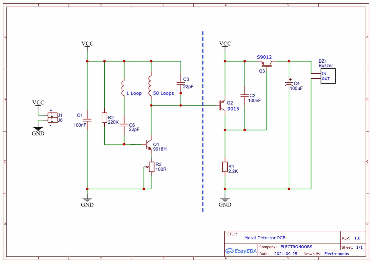
The schematic for this PCB is this one and you could get it from below if you want to use the same values. Also download the GERBER files for the PCB from the next chapter, go to PCBWAY.com, upload the zip file on their website and select the settings such as color, materials, amount of PCBs and so on. Order the PCBs and make this same project an learn something new. The PCB is made out of two parts. All components I've used are through hole. The two coils are already on the PCB so you don't have to add them. All you need are some resistors, capacitors and some BJT transistors. Is very simple!
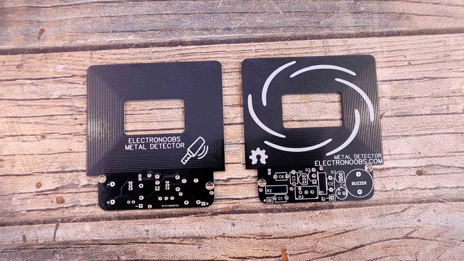
The PCB is made out of two parts. The coils, which is the upper part, and the circuit which is on teh bottom part of the PCB. The coils are winded on both sides of the PCB so the same coil starts on one side and continues to the other side with a total of around 50 loops. You can’t add copper area to the PCB because that would affect the inductance of the coils, so leave only the tracks without any copper around them. According to my tester, the coil has a resistance of around 12 ohms and an inductance of 80uH. Get the GERBER files from below and order yoru own PCB. Go to PCBWAY.com or any other PCB manufacturer, upload the zip file with the GERBERs on their website and select the settings such as color, materials, amount of PCBs and so on.
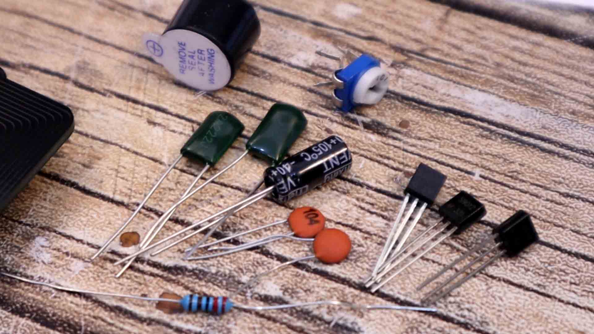
Together with the PCB, to make this project we need a buzzer that will emit the sound when metal is detected. We need 3 BJT transistors, two PNPs and one NPN. Some capacitors, some resistors and a potentiometer. And we need a power source which could be a simple battery. The components list is very short.
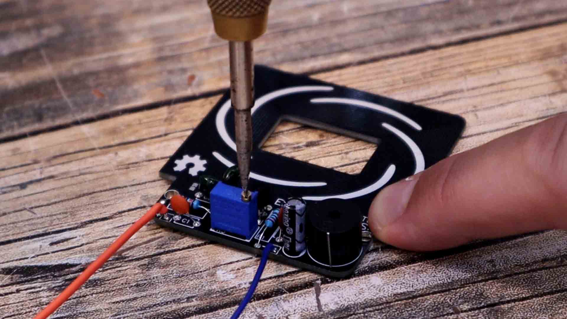
Now let’s assemble the PCB and test it out. Soldering the components is not that difficult since they are all trough hole. So just follow the values on the schematic and solder them one by one. Be careful with the transistors and not solder them backwards. We have a nice silk-layer on the PCB so we can know where each component will go and also the polarity. All the components are now soldered. I remove the buzzer protection. Now we need to adjust the oscillation point. We do that using the potentiometer. As you can see on the schematic, this was connected at the emitter of the first transistor so by changing the potentiometer value we change the amount of current that is passing trough the coil so with that we adjust the amplitude and by that, when the oscillation starts. Supply the circuit with around 5V. You will hear the buzzer beeping. Rotate the potentiometer till the sound stops. This is the where we have the oscillations but amplitude is almost OFF. Now let’s test it.
I get it close to a metal and it beeps, so it works. Even through some material, it can detect the metal, that’s why they use such detectors in airports and detect metals inside people pockets. Now as you can see, the detection distance is not that big. Only a few cm so this circuit is not that sensible. The problem is with the coil on a PCB. Because on the board, the loops are placed side by side so the coil is occupying a lot of area. A coil made with wires could have the same amount of loops but on a smaller area. So with the PCB, when a metal is placed in the middle, only a few turns are near the metal. Making this circuit with external coils made out of copper wire might increase the sensibility. So you can use the same circuit we have here on the PCB but you add your own coils. The inductance of the coil might affect the oscillation speed and so on, so have that in mind.
Instead of a buzzer you can also use an LED so instead of sound alarm you can have a light alarm. So guys, you can get the schematic and the GHERBER files from THIS POST if you want to make the same tests. If my videos help you, consider supporting my work on my PATREON or a donation on my PayPal. Thanks again and see you later guys.