Pulse width modulation (PWM), or pulse-duration modulation (PDM), is a method of reducing the average power delivered by an electrical signal, by effectively chopping it up into discrete parts. The average value of voltage (and current) fed to the load is controlled by turning the switch between supply and load on and off at a fast rate. The longer the switch is on compared to the off periods, the higher the total power supplied to the load. Along with maximum power point tracking (MPPT), it is one of the primary methods of reducing the output of solar panels to that which can be utilized by a battery.[1] PWM is particularly suited for running inertial loads such as motors, which are not as easily affected by this discrete switching, because their inertia causes them to react slowly. The PWM switching frequency has to be high enough not to affect the load, which is to say that the resultant waveform perceived by the load must be as smooth as possible.
The rate (or frequency) at which the power supply must switch can vary greatly depending on load and application. For example, switching has to be done several times a minute in an electric stove; 120 Hz in a lamp dimmer; between a few kilohertz (kHz) and tens of kHz for a motor drive; and well into the tens or hundreds of kHz in audio amplifiers and computer power supplies. The main advantage of PWM is that power loss in the switching devices is very low. When a switch is off there is practically no current, and when it is on and power is being transferred to the load, there is almost no voltage drop across the switch. Power loss, being the product of voltage and current, is thus in both cases close to zero. PWM also works well with digital controls, which, because of their on/off nature, can easily set the needed duty cycle. PWM has also been used in certain communication systems where its duty cycle has been used to convey information over a communications channel.
Source: https://arduinoinfo.mywikis.net/wiki/Arduino-PWM-Frequency
There is a very good tutorial HERE: Credits for the below: http://usethearduino.blogspot.com
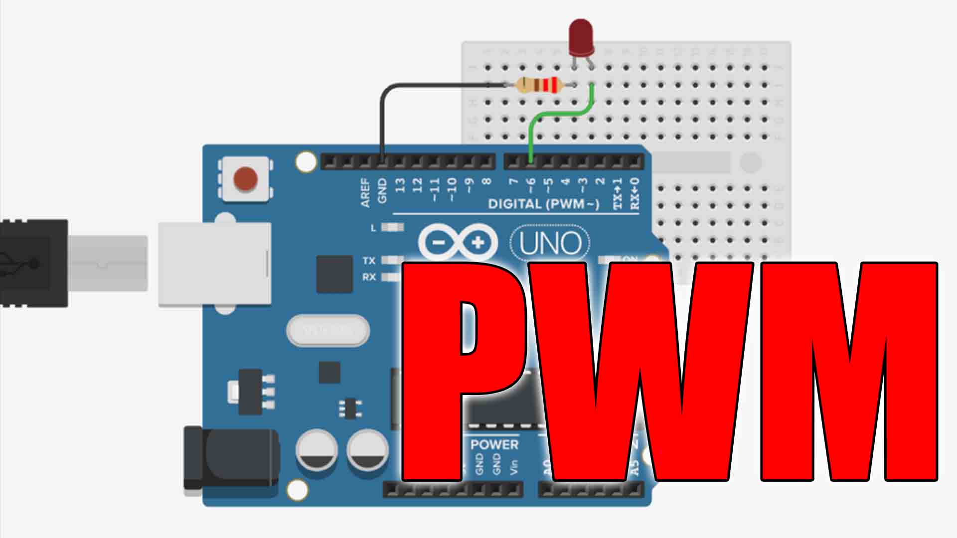
On the Arduino UNO and YourDuino RoboRED etc., pins 3,5,6, 9, 10, 11 can be configured for PWM output. The 8-bit PWM value that you set when you call the analogWrite function: analogWrite(myPWMpin, 128); Outputs a square wave is compared against the value in an 8-bit counter. When the counter is less than the PWM value, the pin outputs a HIGH; when the counter is greater than the PWM value, the pin outputs a LOW. In the example above, a square wave is generated because the pin is HIGH from counts 0 to 127, and LOW from counts 128 to 255, so it is HIGH for the same amount of time it is LOW.
It follows logically that the frequency of the PWM signal is determined by the speed of the counter. Assuming you are using an UNO, this counter’s clock is equal to the system clock divided by a prescaler value. The prescaler is a 3-bit value stored in the three least significant bits of the Timer/Counter register: CS02, CS01, and CS00. There are three such Timer/Counter registers: TCCR0B, TCCR1B, and TCCR2B.
Since there are three different prescalers, the six PWM pins are broken up into three pairs, each pair having its own prescaler. For instance, Arduino pins 6 and 5 are both controlled by TCCR0B, so you can set Arduino pins 6 and 5 to output a PWM signal at one frequency. Arduino pins 9 and 10 are controlled by TCCR1B, so they can be set at a different frequency from pins 6 and 5. Arduino pins 11 and 3 are controlled by TCCR2B, so they may be set at a third frequency. But you can’t set different frequencies for pins that are controlled by the same prescaler (e.g. pins 6 and 5 must be at the same frequency). If you use the default values set by the Arduino Diecimila’s bootloader, these are your PWM frequencies: Arduino Pins 5 and 6: 1kHz. Arduino Pins 9, 10, 11, and 3: 500Hz
In the void setup() part of your Arduino code, set or clear the CS02,CS01, and CS00 bits in the relevant TCCRnB register.
//---------------------------------------------- Set PWM frequency for D5 & D6 -------------------------------
//NOTE: Changing this timer 0 affects millis() and delay!
//TCCR0B = TCCR0B & B11111000 | B00000001;    // set timer 0 divisor to     1 for PWM frequency of 62500.00 Hz
//TCCR0B = TCCR0B & B11111000 | B00000010;    // set timer 0 divisor to     8 for PWM frequency of  7812.50 Hz
  TCCR0B = TCCR0B & B11111000 | B00000011;    // set timer 0 divisor to    64 for PWM frequency of   976.56 Hz (The DEFAULT)
//TCCR0B = TCCR0B & B11111000 | B00000100;    // set timer 0 divisor to   256 for PWM frequency of   244.14 Hz
//TCCR0B = TCCR0B & B11111000 | B00000101;    // set timer 0 divisor to  1024 for PWM frequency of    61.04 Hz


//---------------------------------------------- Set PWM frequency for D9 & D10 ------------------------------

//TCCR1B = TCCR1B & B11111000 | B00000001;    // set timer 1 divisor to     1 for PWM frequency of 31372.55 Hz
//TCCR1B = TCCR1B & B11111000 | B00000010;    // set timer 1 divisor to     8 for PWM frequency of  3921.16 Hz
  TCCR1B = TCCR1B & B11111000 | B00000011;    // set timer 1 divisor to    64 for PWM frequency of   490.20 Hz (The DEFAULT)
//TCCR1B = TCCR1B & B11111000 | B00000100;    // set timer 1 divisor to   256 for PWM frequency of   122.55 Hz
//TCCR1B = TCCR1B & B11111000 | B00000101;    // set timer 1 divisor to  1024 for PWM frequency of    30.64 Hz

//---------------------------------------------- Set PWM frequency for D3 & D11 ------------------------------

//TCCR2B = TCCR2B & B11111000 | B00000001;    // set timer 2 divisor to     1 for PWM frequency of 31372.55 Hz
//TCCR2B = TCCR2B & B11111000 | B00000010;    // set timer 2 divisor to     8 for PWM frequency of  3921.16 Hz
//TCCR2B = TCCR2B & B11111000 | B00000011;    // set timer 2 divisor to    32 for PWM frequency of   980.39 Hz
  TCCR2B = TCCR2B & B11111000 | B00000100;    // set timer 2 divisor to    64 for PWM frequency of   490.20 Hz (The DEFAULT)
//TCCR2B = TCCR2B & B11111000 | B00000101;    // set timer 2 divisor to   128 for PWM frequency of   245.10 Hz
//TCCR2B = TCCR2B & B11111000 | B00000110;    // set timer 2 divisor to   256 for PWM frequency of   122.55 Hz
//TCCR2B = TCCR2B & B11111000 | B00000111; // set timer 2 divisor to 1024 for PWM frequency of 30.64 HzIn the void setup() part of your Arduino code, set or clear the CS02,CS01, and CS00 bits in the relevant TCCRnB register.
//---------------------------------------------- Set PWM frequency for D4 & D13 ------------------------------

//TCCR0B = TCCR0B & B11111000 | B00000001;    // set timer 0 divisor to     1 for PWM frequency of 62500.00 Hz
//TCCR0B = TCCR0B & B11111000 | B00000010;    // set timer 0 divisor to     8 for PWM frequency of  7812.50 Hz
  TCCR0B = TCCR0B & B11111000 | B00000011;    // set timer 0 divisor to    64 for PWM frequency of   976.56 Hz (Default)
//TCCR0B = TCCR0B & B11111000 | B00000100;    // set timer 0 divisor to   256 for PWM frequency of   244.14 Hz
//TCCR0B = TCCR0B & B11111000 | B00000101;    // set timer 0 divisor to  1024 for PWM frequency of    61.04 Hz


//---------------------------------------------- Set PWM frequency for D11 & D12 -----------------------------

//TCCR1B = TCCR1B & B11111000 | B00000001;    // set timer 1 divisor to     1 for PWM frequency of 31372.55 Hz
//TCCR1B = TCCR1B & B11111000 | B00000010;    // set timer 1 divisor to     8 for PWM frequency of  3921.16 Hz
  TCCR1B = TCCR1B & B11111000 | B00000011;    // set timer 1 divisor to    64 for PWM frequency of   490.20 Hz
//TCCR1B = TCCR1B & B11111000 | B00000100;    // set timer 1 divisor to   256 for PWM frequency of   122.55 Hz
//TCCR1B = TCCR1B & B11111000 | B00000101;    // set timer 1 divisor to  1024 for PWM frequency of    30.64 Hz

//---------------------------------------------- Set PWM frequency for D9 & D10 ------------------------------

//TCCR2B = TCCR2B & B11111000 | B00000001;    // set timer 2 divisor to     1 for PWM frequency of 31372.55 Hz
//TCCR2B = TCCR2B & B11111000 | B00000010;    // set timer 2 divisor to     8 for PWM frequency of  3921.16 Hz
//TCCR2B = TCCR2B & B11111000 | B00000011;    // set timer 2 divisor to    32 for PWM frequency of   980.39 Hz
  TCCR2B = TCCR2B & B11111000 | B00000100;    // set timer 2 divisor to    64 for PWM frequency of   490.20 Hz
//TCCR2B = TCCR2B & B11111000 | B00000101;    // set timer 2 divisor to   128 for PWM frequency of   245.10 Hz
//TCCR2B = TCCR2B & B11111000 | B00000110;    // set timer 2 divisor to   256 for PWM frequency of   122.55 Hz
//TCCR2B = TCCR2B & B11111000 | B00000111;    // set timer 2 divisor to  1024 for PWM frequency of    30.64 Hz


//---------------------------------------------- Set PWM frequency for D2, D3 & D5 ---------------------------

//TCCR3B = TCCR3B & B11111000 | B00000001;    // set timer 3 divisor to     1 for PWM frequency of 31372.55 Hz
//TCCR3B = TCCR3B & B11111000 | B00000010;    // set timer 3 divisor to     8 for PWM frequency of  3921.16 Hz
  TCCR3B = TCCR3B & B11111000 | B00000011;    // set timer 3 divisor to    64 for PWM frequency of   490.20 Hz
//TCCR3B = TCCR3B & B11111000 | B00000100;    // set timer 3 divisor to   256 for PWM frequency of   122.55 Hz
//TCCR3B = TCCR3B & B11111000 | B00000101;    // set timer 3 divisor to  1024 for PWM frequency of    30.64 Hz


//---------------------------------------------- Set PWM frequency for D6, D7 & D8 ---------------------------

//TCCR4B = TCCR4B & B11111000 | B00000001;    // set timer 4 divisor to     1 for PWM frequency of 31372.55 Hz
//TCCR4B = TCCR4B & B11111000 | B00000010;    // set timer 4 divisor to     8 for PWM frequency of  3921.16 Hz
  TCCR4B = TCCR4B & B11111000 | B00000011;    // set timer 4 divisor to    64 for PWM frequency of   490.20 Hz
//TCCR4B = TCCR4B & B11111000 | B00000100;    // set timer 4 divisor to   256 for PWM frequency of   122.55 Hz
//TCCR4B = TCCR4B & B11111000 | B00000101;    // set timer 4 divisor to  1024 for PWM frequency of    30.64 Hz


//---------------------------------------------- Set PWM frequency for D44, D45 & D46 ------------------------

//TCCR5B = TCCR5B & B11111000 | B00000001;    // set timer 5 divisor to     1 for PWM frequency of 31372.55 Hz
//TCCR5B = TCCR5B & B11111000 | B00000010;    // set timer 5 divisor to     8 for PWM frequency of  3921.16 Hz
  TCCR5B = TCCR5B & B11111000 | B00000011;    // set timer 5 divisor to    64 for PWM frequency of   490.20 Hz
//TCCR5B = TCCR5B & B11111000 | B00000100;    // set timer 5 divisor to   256 for PWM frequency of   122.55 Hz
//TCCR5B = TCCR5B & B11111000 | B00000101;    // set timer 5 divisor to  1024 for PWM frequency of    30.64 Hz