A boost converter (step-up converter) is a DC-to-DC power converter that steps up voltage (while stepping down current) from its input (supply) to its output (load). It is a class of switched-mode power supply (SMPS) containing at least two semiconductors (a diode and a transistor) and at least one energy storage element: a capacitor, inductor, or the two in combination. To reduce voltage ripple, filters made of capacitors (sometimes in combination with inductors) are normally added to such a converter's output (load-side filter) and input (supply-side filter).
In this tutorial we will learn how to build and how a DC to DC boost converter works. The circuit is very basic using just one diode, an inductor and a capacitor. The switch will be a MOSFET transistor and to create the PWM signal we will use a 555 timer in the PWM configuration, boost adjustable controller or one Arduino NANO. But first let's study a little bit of theory. We have the Boost converter circuit in the next figure where we can see the switch, inductor and capacitor and of course we add a load to the output.

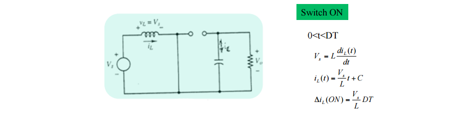
Ok, so we have the next circuit. In order to study how it works, we will divide it in two stages. The ON and OFF stages. In the ON part, the switch is closed as we can see in the next figure where the diode is open becasue the cathode voltage is higher than the anode. The key principle that drives the boost converter is the tendency of an inductor to resist changes in current by creating and destroying a magnetic field. In a boost converter, the output voltage is always higher than the input voltage. When the switch is closed, current flows through the inductor in clockwise direction and the inductor stores some energy by generating a magnetic field. Polarity of the left side of the inductor is positive. So in this case we obtain the current through the inductor using the next formulas.
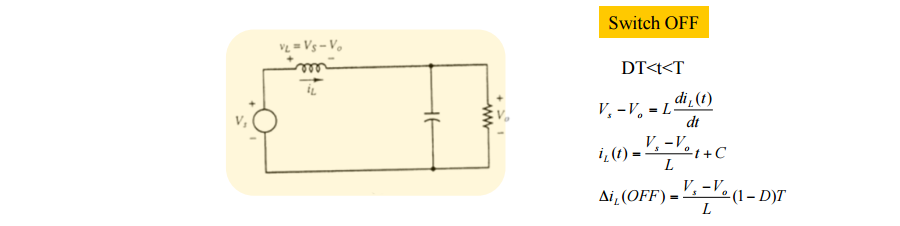
When the switch is opened, current will be reduced as the impedance is higher. The magnetic field previously created will be destroyed to maintain the current towards the load. Thus the polarity will be reversed (means left side of inductor will be negative now). As a result, two sources will be in series causing a higher voltage to charge the capacitor through the diode D. In this case the voltage across the inductor is the diffrence between the output voltage and the input. So once again using the next figure formulas we obtain the current of the OFF part depending on the duty cycle.
Ok, now if we want to obtain the output depending on the input and the duty cycle of the PWM all we have to do is to make the sum of the On and Off current equal to 0. That means that the On current is equal to the Off current. So that will give us:
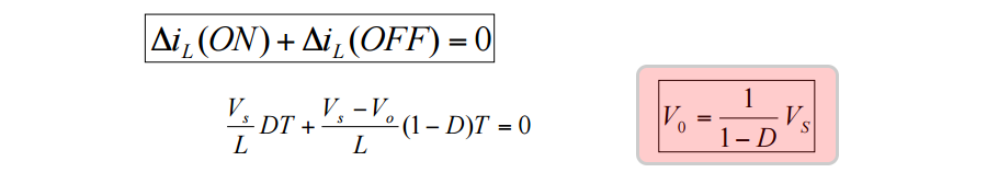
So we've obtain that the output is depending of the duty cycle disproportionate. So the bigger the Duty cycle gets, the higher will be the output. The duty cycle of the PWM can have values between 0 and 1. So the only posible output will be equal or higher than the input. That's why this configuration is called step up converter.
This 555 configuration will create a PWM signatl and apply that signal to the MOSFET gate. The circuit works ok but it has a big problem. The output will change if we change the output load because the circuit has no feedback. Ok so we will use the next schematic for our boost converter example. To create the PWM signal we will use the 555 timer with the PWM configuration. With the P1 potentiometer we can change the duty cycle of the PWM signal, and at the same time the output value. For the MOSFET you could use both IRFL3205 or the IRF44N. You could always try different inductance values for the inductor and see the results.
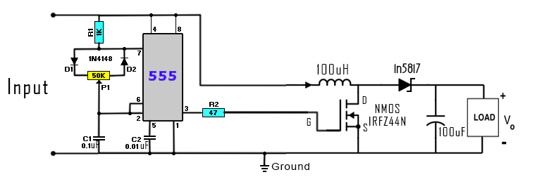
The input could be up yo 15 volts. Don't apply higher voltage or you could burn the 555 timer. Connect the PWM (pin 3 of the 555 timer) to the MOSFET (switch) gate. Add an output load and test the circuit. You could obtain output values higher than the input.
With this component we have feedback and the output will stay the same using different loads. Just make the connections, add the input capacitor to have a steady input and you're done.
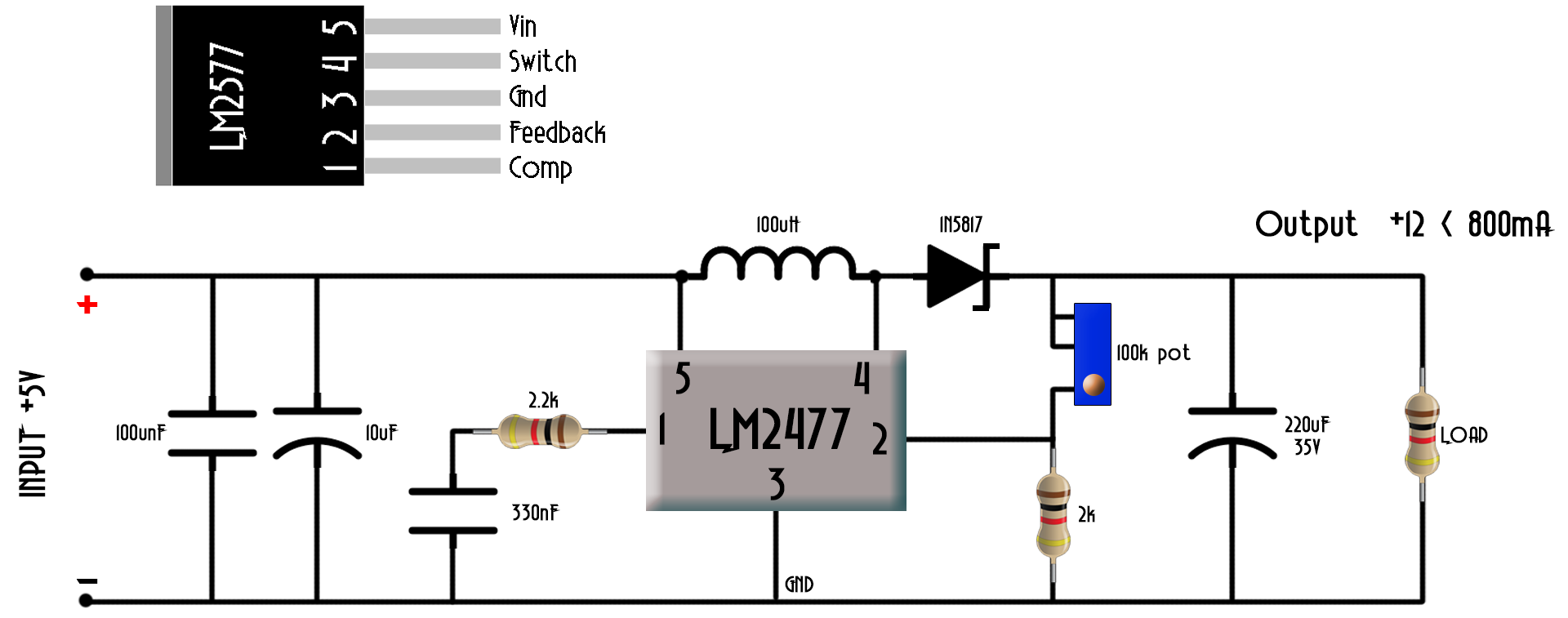
As you can see in the schematic above we have a potentiometer connected to the analog input A0. With this potentiometer we will choose the output value between 1 and 12 volts since the maximum input voltage in this case is 12V. With The input could up to 12 volts. Don't apply higher voltage or you could burn LM2577-ADJ component. In this case we need no external switch since the LM2577-ADJ already has it inside it. With the feedback pin connected to the output voltage divider, the LM2577-ADJ will change the width of the pulse depending of the output in order to keep it constant. In this case use a Schottky Barrier Rectifier diode because it has a low forward voltage. This diode will live the current flow when the switch is open.
Sincerely, this circuit has no sense but to learn. The Arduino NANO already has a 5V linear voltage regulator that will lower the efficiency of the circuit. So the main goal is to learn how the circuit, the feedback and the PWM signal work in order to achive the desired output.
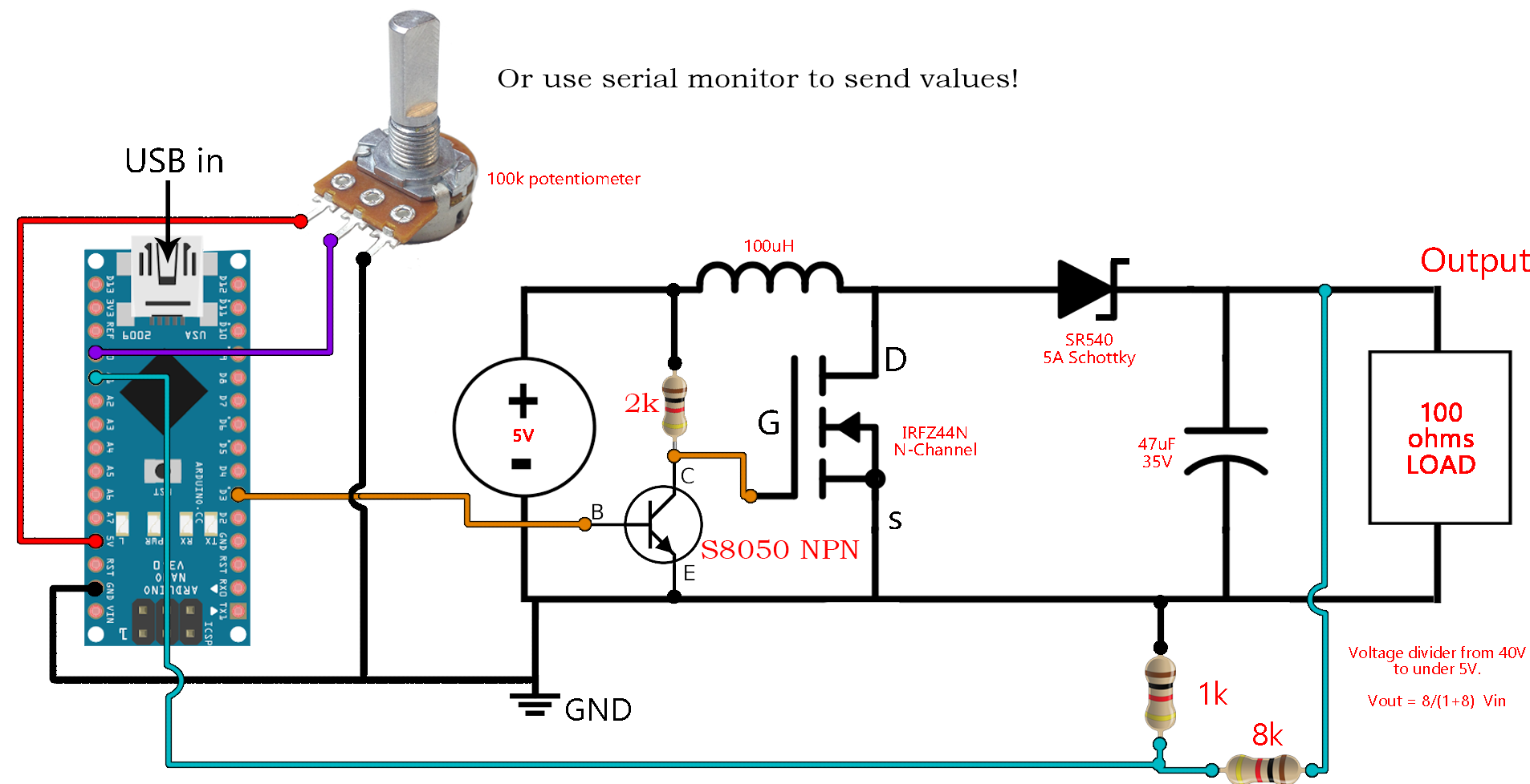
As you can see we have a potentiometer connected to the analog input A0. With this potentiometer we will choose the output value between 1 and 50 volts aprox (your output values may vary). At the output of the circuit we have a voltage divider that will lower the voltage from maximum 50V to under 5 volts because that's the maximum input voltage of the Arduino ADCs. In the code we compare this two voltages and increase or decrease the PWM width in order to keep the output constant. Just copy and upload the next code to the Arduino for this example.
/*
 * This is an example code for a BOOST converter circuit made with arduino + feedback
 * I've used arduino NANO. We have to set the timer of the PWM on pin D3
 * The feedback is connected to A1 and we set the desired voltage with a
 * potnetiometer connected to A0.
 *
 * Subscribe: http://www.youtube.com/c/electronoobs
 * webpage: http://www.electronoobs.com/eng_circuitos_tut10.php
 */


int potentiometer = A0; //The input from the potentiometer is A0
int feedback = A1;      //The feedback input is A1
int PWM = 3;            //Digital pin D3 por PWM signal
int pwm = 0;            //Initial value of PWM width

void setup() {
  pinMode(potentiometer, INPUT);
  pinMode(feedback, INPUT);
  pinMode(PWM, OUTPUT);
  TCCR2B = TCCR2B & B11111000 | B00000001;    // pin 3 and 11 PWM frequency of 31372.55 Hz
}

void loop() {
  float voltage = analogRead(potentiometer);    //We read the value of the potentiometer, which is the desired value
  float output  = analogRead(feedback);         //We read the feedback, which is the real value

  //If the desired value is HIGHER than the real value, we increase PWM width
  if (voltage > output)
   {
    pwm = pwm+1;
    pwm = constrain(pwm, 1, 254);
   }

  //If the desired value is LOWER than the real value, we decreaase PWM width
  if (voltage < output)
   {
    pwm = pwm-1;
    pwm = constrain(pwm, 1, 254);
   }

   analogWrite(PWM,pwm);  //Finally, we create the PWM signal
}
If my videos help you, consider supporting my work on my PATREON or a donation on my PayPal. Thanks again and see you later guys.