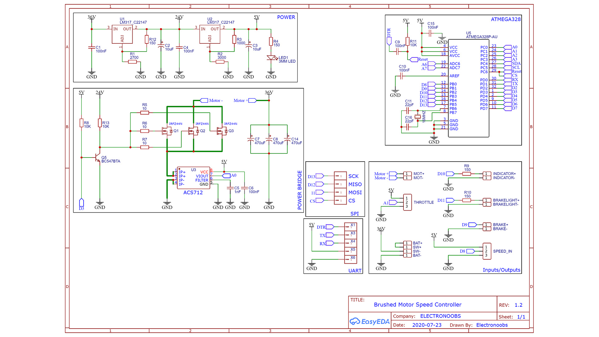
You have the scheamtic below. Remember that instead of the BC547 BJT you could add a MSOFET driver supplied at 24V and connected to the MOSFETs gate. The BJT has a pullup so it will be activated when the PCB starts, so the MOSFET gates are connected to GND, so those will be OFF. We don't want the MSOFETs to be ON for a short moment till the Arduino starts-up. The first part you will want to mount on the PCB is the "POWER" with the LM317 regulators. In this way, if the supplies fails and the output is higher than 5V, we won't burn the other components... Then add the ATmega328 basic configuration and then the rest of components.