So, for some time I've been working on a good Arduino based, brushed coreless DC motors, NRF24 radio connection drone that could also have everything on the same PCB. After a few attempts, I finally have a good enough version. This drone flies very well, the code is based on the MultiWii platform, all components are on the drone PCB, everything is explained in this tutorial and you also have the parrt list below. So, if you want to make the same, follow this tutorial. The radio controller is also based on arduino and we've made it in a past tutorial. This kit would also have a PCB for the radio controller but if you want a bigger and better one, just check the previous tutorial. So, let's see how this works and how to mount it.
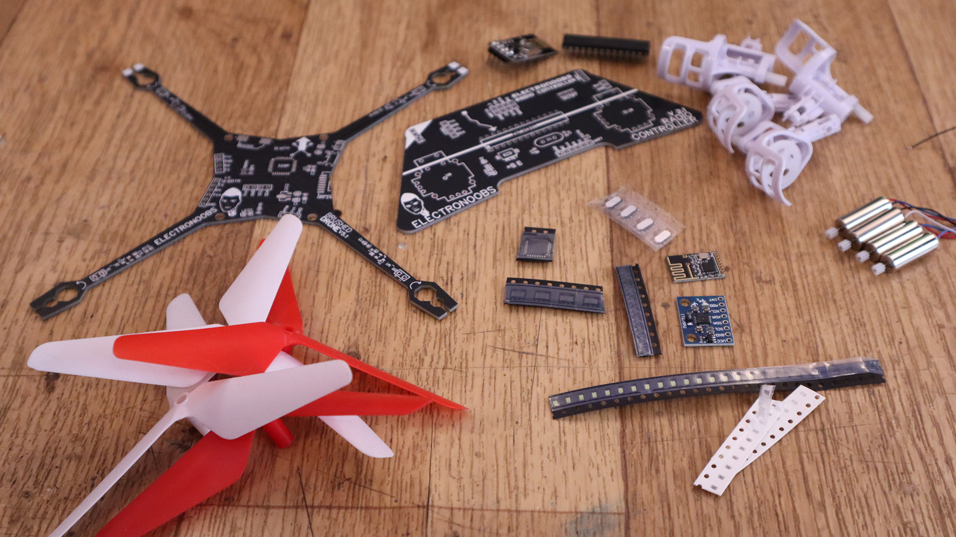
We need a lot of parts but don't worry, nothing complicated to get. We need the ATmega328 chip in AU package, the sensor, the motors, propellers, the radio module and a few other SMD components such as ressitors, capacitors and LEDs. Check each component below. If the link is not updated, jsut go on eBay adn search the component yourself using the names below.
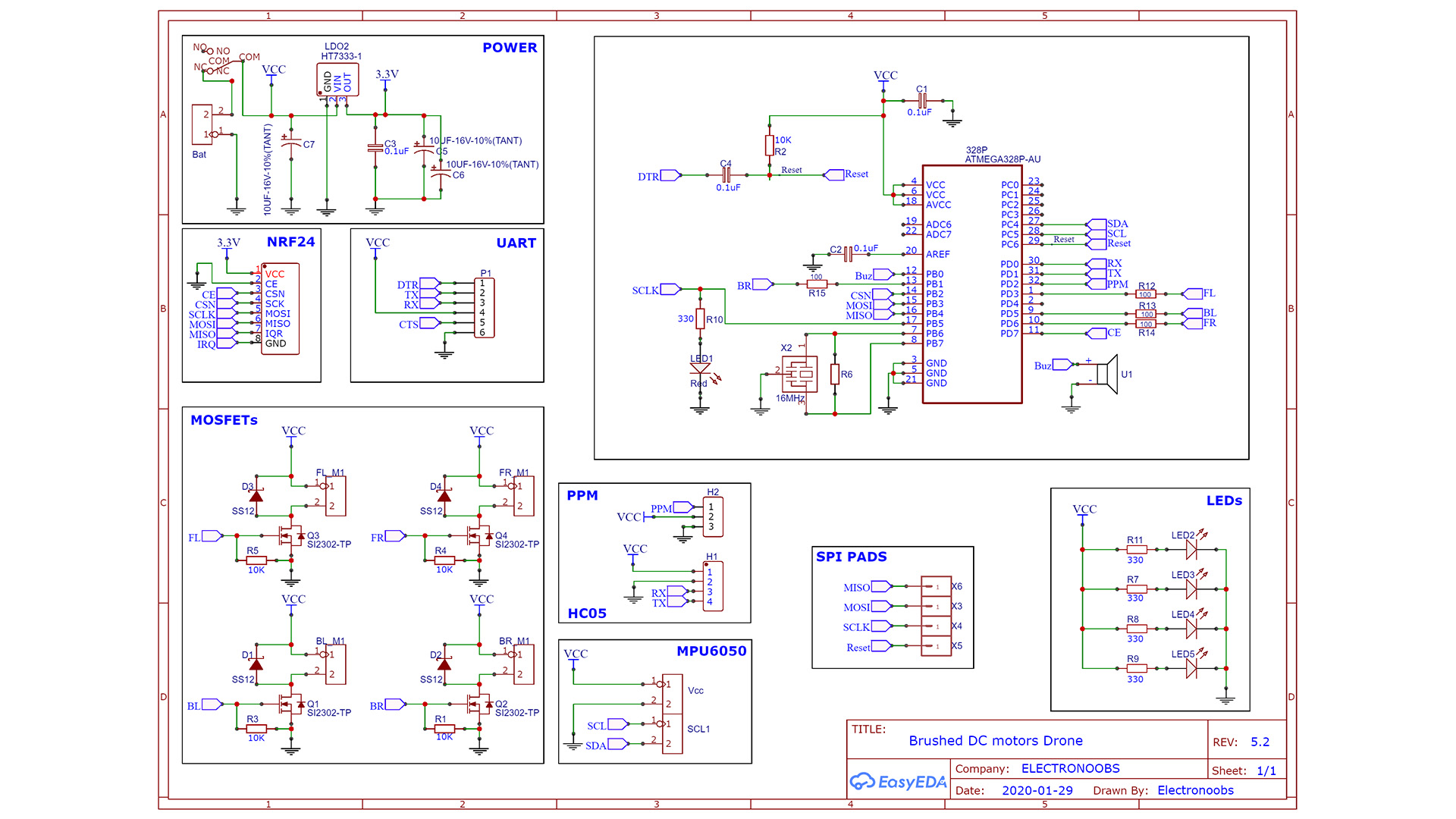
The schematic is not that difficult and is quite the same as the other version. First we have the power block where we regulate our 3.3V for the NRF24 radio module. Remember that this module needs that voltage. The ATMega328 chip needs a few components to work such as the reset pullup, the crystal and other capacitors. To control the motors we use 4 n-MOSFETs. The PCB also has SPI pads in case you need to butnj the bootloader to the new chip. Get the PCB and the components and following the values on the schematic, solder the PCB.
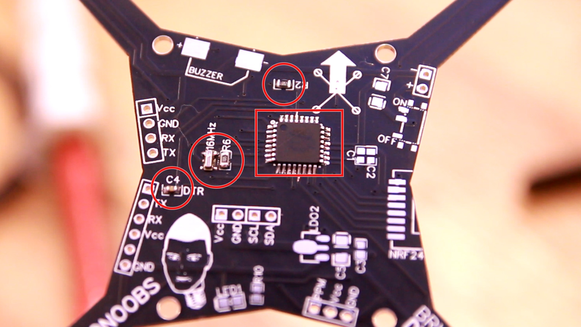
First of all, we need to solder the microcontroller and test it. Is the most delicate component and we must make sure it has a bootloader, the crystal is working and the basic configuration is ok. So first step, get the drone PCB and the next components: The ATmega328-AU chip, the R2 resistor of 10K, the 16MHz crystal and the R6 resistor of 1M and finally the C4 capacitor of 100nF. With these components we can test the microcontoller. So, solder all these components. Follow the dot on the microcontroller in order to know which is the first pin. I've used solderpaste and my hot air gun to solder the chip and crystal and the soldering iron for the rest of the components.
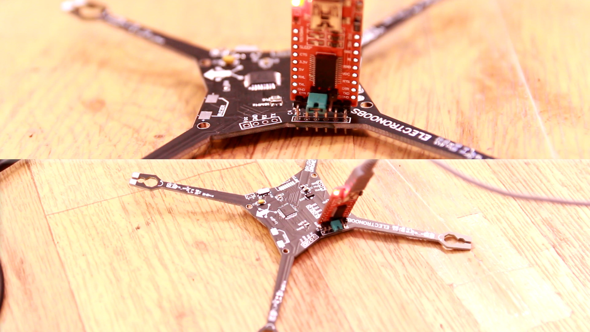
In my case, I've took out the ATmega328-AU chip from an Arduino NANO board. That means it already has a bootloader so we could directly test it with the FTDI programmer. If it's a brand new chip taht you bought, you need to burn the bootloader first, so check next part for that. If the chip has the bootloader, connect the FTDI programmer to the UART port with Vcc, GND, RX, TX and DTR pin. Select Arduino NANO board in the Arduino IDE, select the COM of the programmer and upload any simple sketch in order to test if the chip works. I usually upload a counter with Serial.print so I can check that counter value on the serial monitor (see code below). If it works, everything is good and we can keep soldering components. If it doesn't work it might be because:
- The chip dose not have a bootloader (you will get not in sync error)
- The DTR capacitor is not 100nF value or not well soldered so the FTDI can't make a propper reset
- The R2 resistor is not well soldered so we don't have the reset pin with pullup
- Any of the ATmega238-AU pins could not be well soldered (check with multimeter)
- The crystal could not be of 16MHz or now well soldered in place
- You've damaged the chip (get a new one and lower the temperature while soldering)
int x = 0;
void setup() {
  Serial.begin(9600);
}
void loop() {
  Serial.println(x);
  x++;
  delay(1000);
}
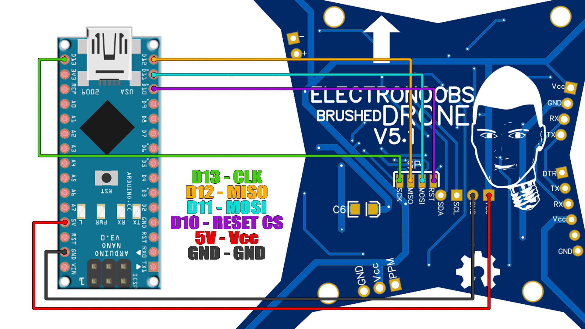
If the ATmega328-AU chip is brand new, you will probably need to burn a bootloader to it. With the same configuration as above we can burn the bootloader so solder the chip and components as before. You will need an Arduino NANO to burn the bootlaoder. Make the connections as below from the Arduino NANO to the bottom side of the PCB. Connect GND and 5V to any of the GND and Vcc pins of the PCB.
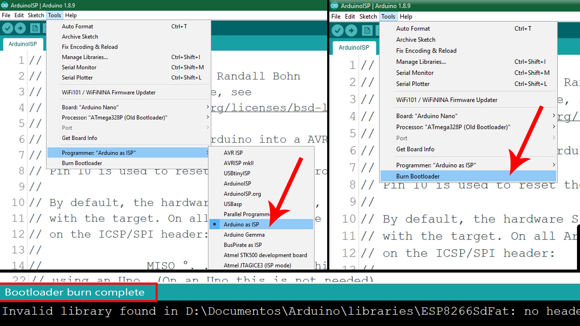
Ok, once you have the Arduino NANO connected to the PCB you need to prepare it to work as an ISP programmer. For that you need yo upload the Arduino as ISP code to the NANO first. So, go on the Arduino IDE, examples, ArduinoISP and open that example sketch. Then select the Arduino NANO board and the default programmer type. Upload this code to the NANO.
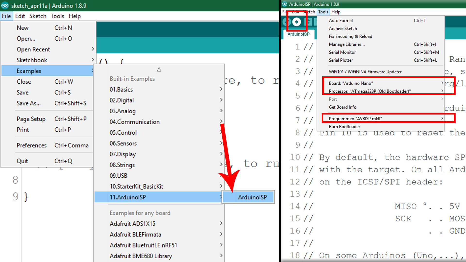
Now that the Arduino ISP code is uploaded and the connections are made, is time to burn the bootloader. First, change the programmer type from default to Arduino as ISP as you can see below. Then go to tools and click burn bootloader. The LEDs of the Arduino NANO should blink like crazy. After that you should get the message Bootloader burn complete if everything goes well. To test the chip, change back the programmer to AVRISP MKII and follow the step before (3.2) and using the FTDI programmer, upload a test sketch.