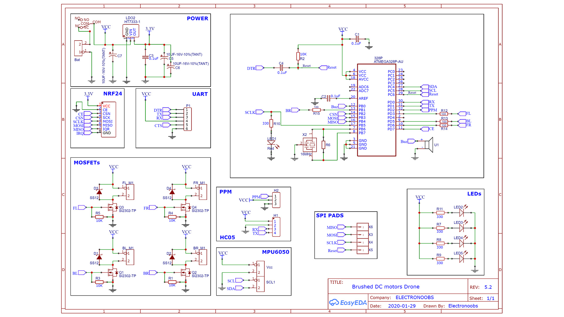
The schematic is not that difficult and is quite the same as the other version. First we have the power block where we regulate our 3.3V for the NRF24 radio module. Remember that this module needs that voltage. The ATMega328 chip needs a few components to work such as the reset pullup, the crystal and other capacitors. To control the motors we use 4 n-MOSFETs. The PCB also has SPI pads in case you need to butnj the bootloader to the new chip. Get the PCB and the components and following the values on the schematic, solder the PCB.