In this tutorial we first learn what is a strain gauge and how it works. Then, sicne the gauge works with resistance variations, we learn how to pass from resistance changes to voltage values. Then, using a 24bit ADC, we read that voltage and in this way we can measure deforamation of certain materials. Using this deformation, with a lineal curve, we pass that to force and by taht to weight. So, like that we can build a simple precision scale uisng the Arduino taht will read the values from the 24bits ADC. Let's start.
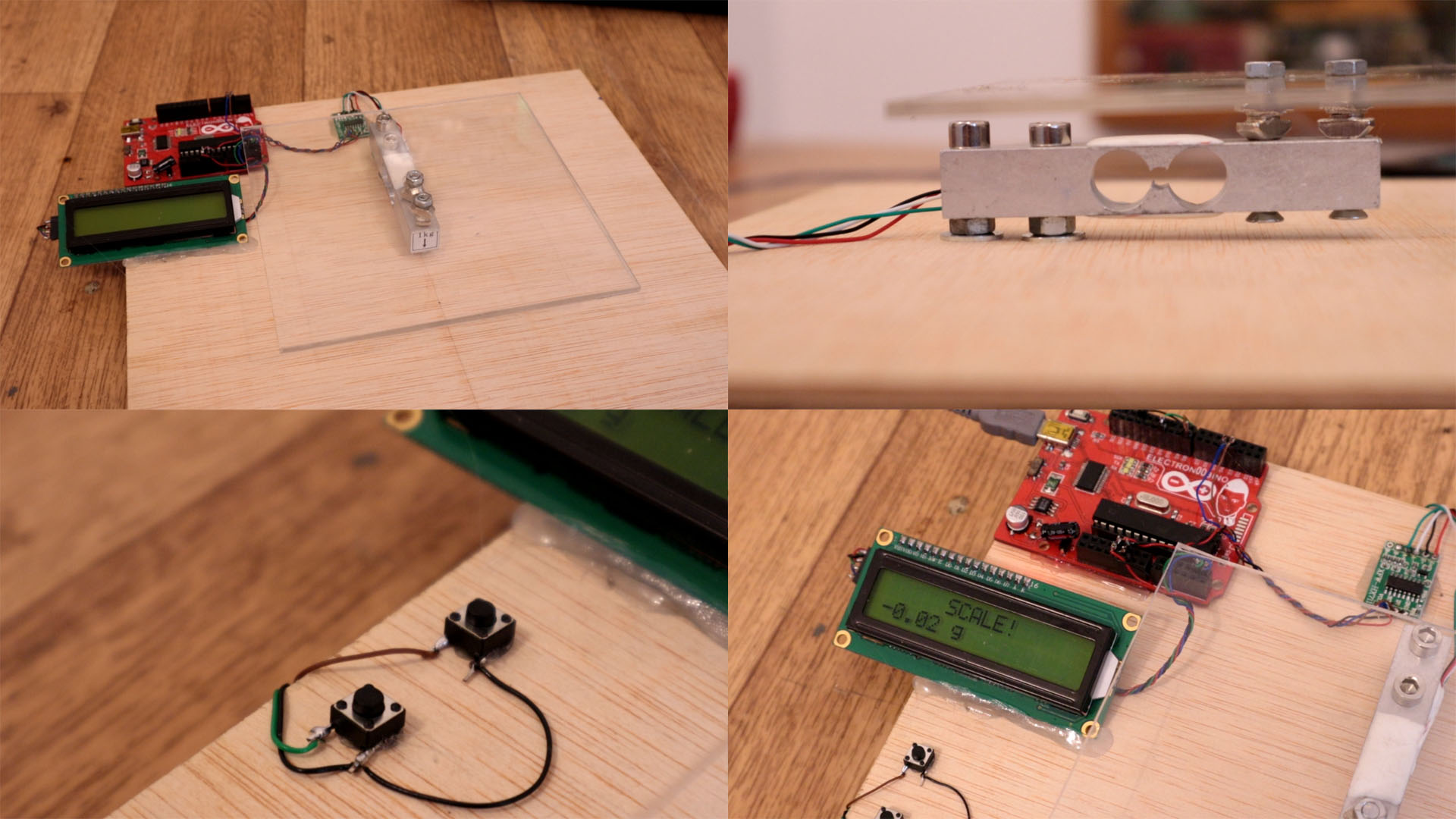
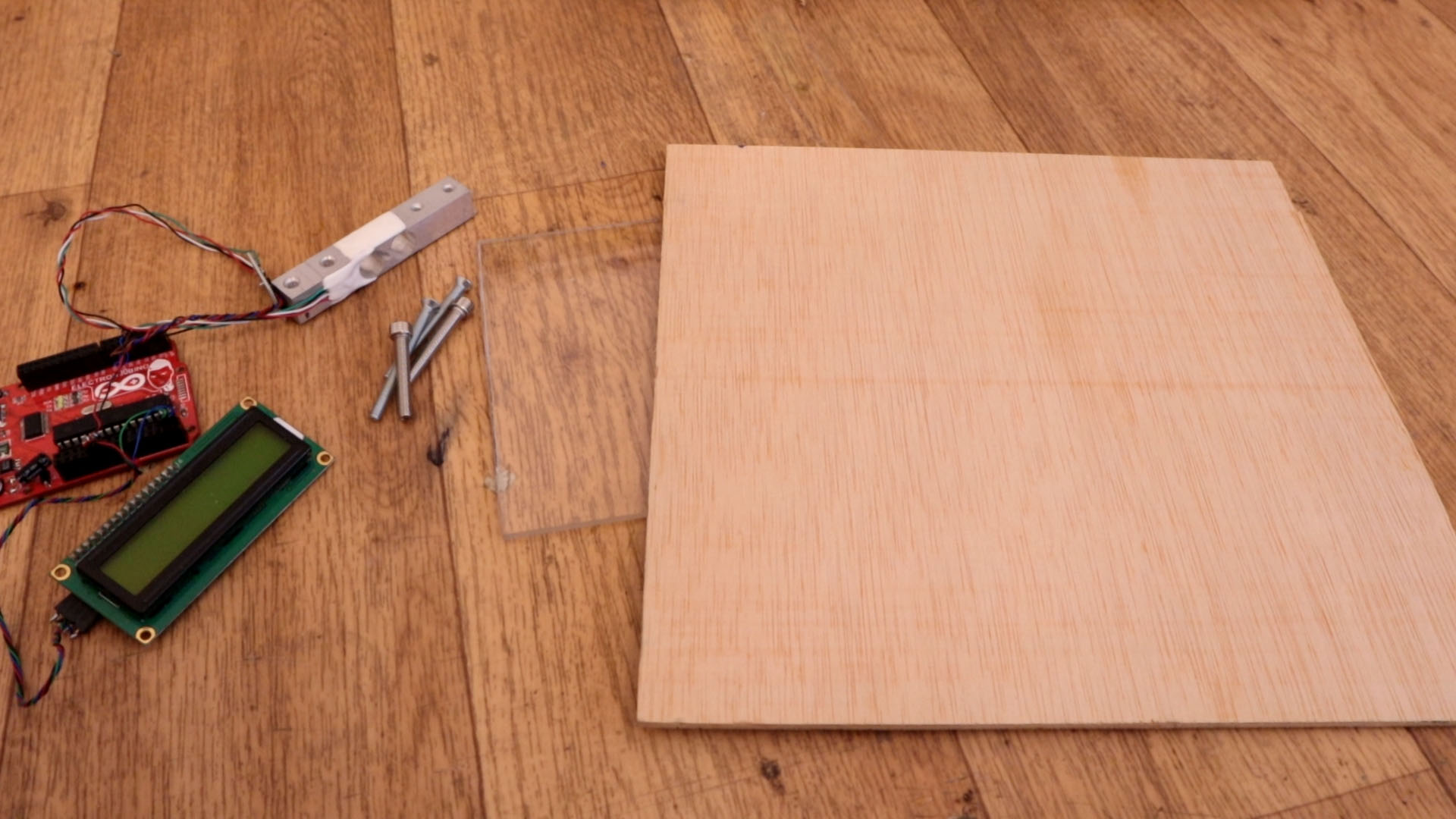
Part list is very short. We need the Arduino that will process the data. Then we need a load cell, in my case I wanted a low weight precision scale so I've selected a 1Kg laod cell. In your case you could go with any other. Then we need the HX711 24bits ADC to read the voltage value, an LCD screen with i2c to print the weight and two push buttons. We will also need some screws, a plywood for the base and the acrilic part for the top side of the scale. The rest are just wires. That's it.
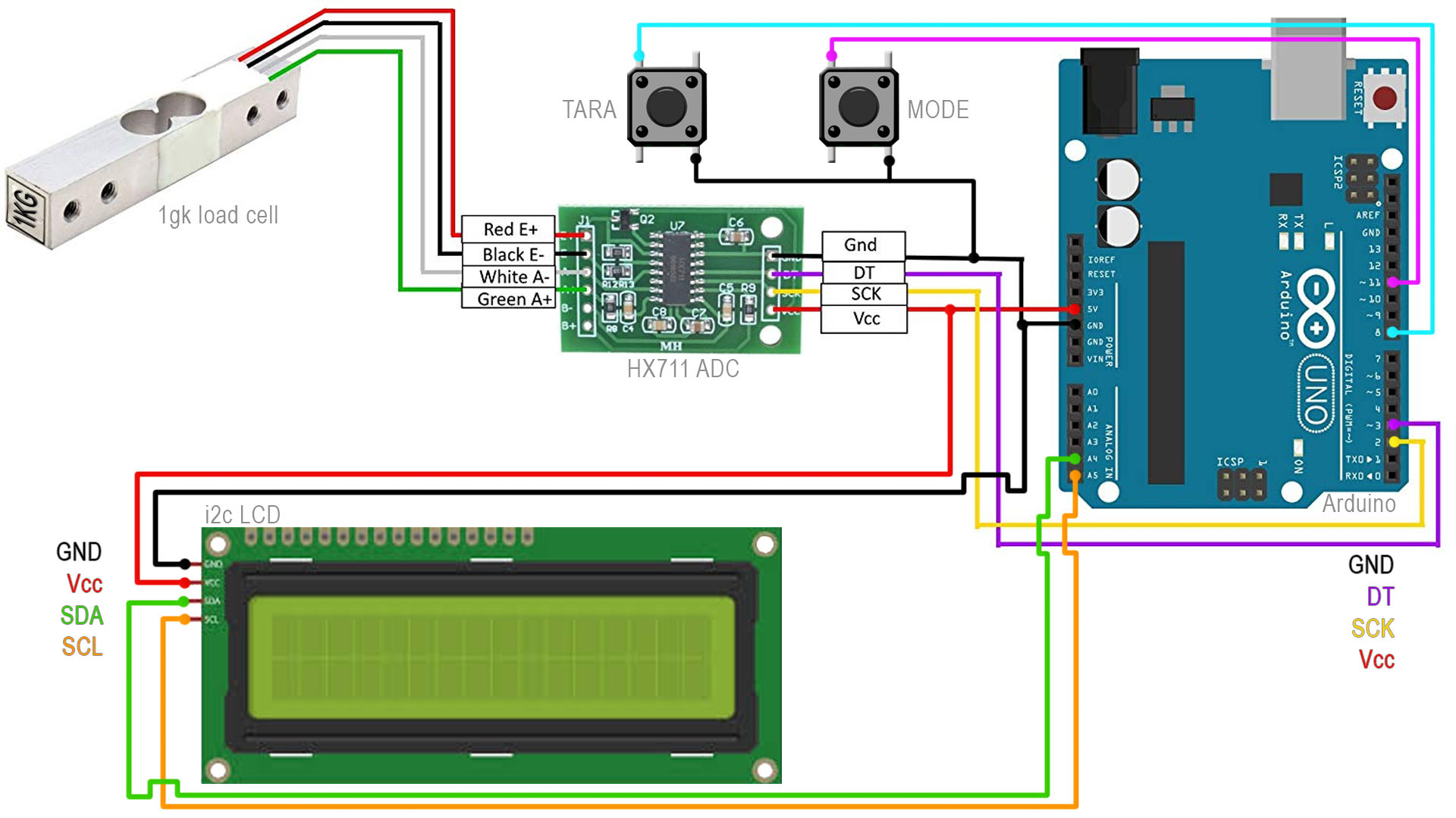
We can supply everything with 5V so don't worry. Connect GND and 5V to the LCD and the HX711 ADC. Connect one side of the push buttons to GND and the other side, one to D8 and the other button to D11 of the Arduino. Connect data and clock for the LCD to pins A4 and A5 and also data and clock from the ADC to pins D3 and D2. Connect the laod cell as below, and follow the color of the wires.
Ok, with the same setup in the schematic above, run the enxt code and see the raw value from the HX711 ADC. You will get values from 0 to 2 exponential 24 because is a 24 bits. So we will have decent precision. Also when the bridge is balanced, we will be in the middle value so we can go both positive and negative meaning positive or negative forces on the load cell. Intall the library and run the example code below then open the serial monitor.
#include <Q2HX711.h>                              //Download it here: https://electronoobs.com/eng_arduino_hx711.php
const byte hx711_data_pin = 3;
const byte hx711_clock_pin = 2;
Q2HX711 hx711(hx711_data_pin, hx711_clock_pin);
void setup() {
  Serial.begin(9600);
}
void loop() {
  Serial.println(hx711.read()/100.0);
  delay(500);
}
The code is quite simple. You can go below and download it and you will also have links for the libraries for the LCD screen and the HX711 ADC. In the code we first wait for the ADC value to cahnge a lot. That means the calibration mass was placed on the scale. Then we create a loop and calibrate the scale based on that calibrated mass. Change the "y1" value to the value (in grams) of your calibrated mass. Then in the code, we just read the value and print it on the LCD or serial monitor. We also have interuptions for the two push buttons to detect when we press the mode or Tara buttons. The Tara will set the scale to 0, and the mode will change from g, to mm and to oz. Install the libraries, compile and upload to the Arduino. Remember to change the "y1" variable you can see below with the weight of your own calibrated mass.
//Variables
/////////Change here with your calibrated mass////////////
float y1 = 2831.0; // calibrated mass to be added
//////////////////////////////////////////////////////////

long x1 = 0L;
long x0 = 0L;
float avg_size = 10.0; // amount of averages for each mass measurement
float tara = 0;
bool tara_pushed = false;
bool mode_pushed = false;
int mode = 0;
float oz_conversion = 0.035274;
//////////////////////////////////////////////////////////
As you can see below, the setup is easy. First screw the load cell in palce. I add two screw nuts so it will have clearance from the ground so it will be able to flex. Then I screw that to the plywood and on top I add the acrylic. Connect the wires as in the scheamtic. Add the push buttons and I glue everything on the plywood board. Upload the code, after the "add calibrated mass" message add your mass, and the scale will be ready. I supply my setup with the USB cable.