
 About me
  History
  Let's learn
  Contact us
  Arduino tutorials
 Circuits tutorials
  Robotics tutorials
 Q&A
Q&A Blog
Blog  Arduino
  Circuits
 Robotics
  Modules
  Gadgets
  Printers
  Materials
  3D objects
  3D edit
  Donate
  Reviews
  Advertising


Arduino multimeter BASIC

Current meter
There are aleready a lot of dedicated sensors to measure current - such as the Allegro Microsystems ACS712 (as used in my Power Supply Project). But in this project we will build our own curent meter using Arduino microcontroller. Using a shunt provides a lot more flexibility in the current range that's available, rather than being "stuck" with the 5A or 30A ranges of the dedicated Hall Effect sensors.
Evrubody knows OHM LAW. The voltage drop between two terminals equals to the current value multiplied by the resistance between those two terminals.
So using this simple equation it is very easy to measure the current that flows between the two terminals of a resistor.
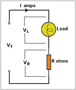
In this figure we can see that we are applying a voltage VT to a load, in this case a light bulb and a resistor in series. We want to measure the current that flows trough the light bulb which is the same that flows throug the resistor because they are conected in series. So if we know the resistance of the resistor and we measure the voltage drop between it's terminals , we could calculate the current using the OHM LAW above. The problem is that we need to use a low resistance resistor because if not, the resistor voltage drop would effect the voltage that we whant to apply to the light bulb.
For exampe let's say that we want to apply 12 volts to the light bulb. And the current that flows is about 1 amper. If the resistor values is, let's say 10 ohms, that would create a voltage drop VR between ground and the middle terminal of the resistor of 10 volts which means that we won't apply 12 volts VL to the light any more. We will apply only 12-10=2 volts which is not what we want.
To solve this problem we won't use a normal resistor. The solution is to use a shunt resistor with very low values of resistance. Very low Ohmic value resistors are available especially for this purpose and are generally known as shunts. The name is derived from their use with older moving coil type ammeters where a shunt is wired directly across the ammeter terminals. It's purpose is to 'shunt' most of the circuit current away from the ammeter which, itself, is designed to handle only a few milliAmps to deflect the needle fullscale.
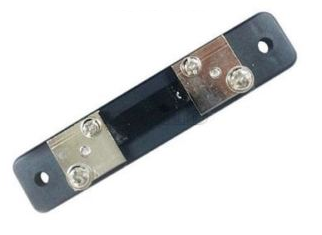
I bought this shunt from eBay. When you buy them you must look at it's specifications. This is an example of a shunt specifications.
Current: 10A.
Voltage Drop: 75mV.
Accurancy: 0.5 Class.
Environmental conditions: -40~+60°C, the relative temperature ≤ 95%(35°C).
Several parameters are important to specify a shunt resistor. Shunt resistors have a maximum current rating. The resistance value is given by the voltage drop at the maximum current rating. For example, a shunt resistor rated with 100A and 50mV has a resistance of 50 / 100 = 0.5 mOhm. The voltage drop at maximum current is typically rated 50, 75 or 100 mV. In this case our shunt is a 10A and a maximum voltage drop of 75mA. That gives us a resistance of :
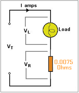
So now we have our circuit with a very low resistance shunt resistor. Now if we have 1A of current flowing the voltage drop at the shunt resistor wold be just 7.5mV which won't effect the 12 volts that we want to apply to the light bulb.
But now we have another problem. In order to measure the current we have to measure the VR voltage drop first and divide that by the resistance value. But with souch a low resistance the voltage drop is so small that our Arduino ADC will only be able to measure huge steps of current values.
As we sad, for example, we want to measure 1A of current. That will make a 7.5mV drop at VR. The Arduino ADC has 10 bits. That means it will give a 0 value for o volts and 1024 for 5 volts which is the maximum Vref voltage of this microcontroller.
0.0075volts ------- X
If we calculate "X" that would give us 1.5 units of the ADC for a 7.5mV voltage drop. That basically means that we will be able to measure just 1A jumps of current values. In order to be able to measure with a lot more precision we have to amplify this voltage drop. To do that we will use an instrumentational amplifier. We won't use a simple OPAMP because we need a high gain and a lot of precission. Normal OPAMPS usually have a lot of error. We will use the AD623AN instrumentational amplifier. As can be seen from the datasheet, its gain is set with a single 1% resistor (or, perhaps, a preset variable resistor if you want to change the gain any time).
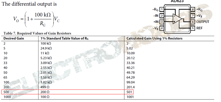
If we take a look at the AD623AN datasheet we can see that the gain depends of the Rg resistor between pins 1 and 8. We know that our maximum voltage drop betwee the shunt terminals will be 7.5mV for 10 ampers. Using a 500 gain we will have 3.75 volts output from the amplifier which would be great for our Arduino's ADC. But souch a high gain could give us errors. Always look at the datasheet to see the error graph for each gain. So for a 501 gain we have to use a 200 ohm Rg resistor. We should add a 100 ohm potentiometer as well for fine tunning.
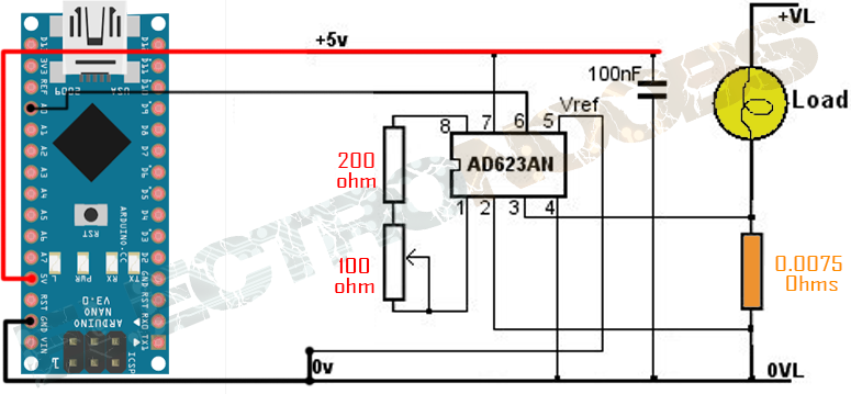
So we supply the amplifier with 5 volts from the arduino because it won't use too much current. The amplifier will amplify the voltage drop between the shunt terminals. Now we can measure that voltage drop with a range between 0 and 5 volts. Set the gain of the amplifier in souch a way that when we have our maximum 10A of current the output voltage will be below 5 volts. Now all we need to do is to upload the next code to our arduino and start measureing current. Remember to instal the lyquid crystal i2C library in order to use the i2c LCD screen.
You can download the
To install it we just go to Sketch -> Include library and we open the .zip file that we've just downloaded.
/*Thanks. Remember to visit my Youtube channel
  I've used a i2c LCD screen module.
*/
//LCD config
#include <Wire.h>
#include <LiquidCrystal_I2C.h>
LiquidCrystal_I2C lcd(0x3f,20,4);  //sometimes the adress is not 0x3f. Change to 0x27 if it dosn't work.
////////////////////////////////////////////////////////////////////////////////////////////////////////

int analogInputAmps = A3; //Connect the output of the amplifier to this pin

 int readAmpsADC = 0;
 float voltage = 0.0;
 float amps = 0.0;

void setup(){
   pinMode(analogInputAmps, INPUT);
   lcd.init();
   }

float fmap(float x, float in_min, float in_max, float out_min, float out_max) {
  return (x - in_min) * (out_max - out_min) / (in_max - in_min) + out_min;
}

void loop() {
   readAmpsADC = analogRead(analogInputAmps);
   voltage = fabs(fmap(readAmpsADC, 0.0, 1024.0, 0.00, 5.0)); //this maps the measured voltage in volts from 0 t 5V
   amps = voltage * (10.0/3.7575); //Because we have 10A when the voltage is 3.7575 for a 501 gain (0.0075V * 501)

   lcd.setCursor(0,0);
   lcd.print("SCALE:    0A-10A");
   lcd.setCursor(0,1);
   lcd.print(amps,3);
   lcd.setCursor(15,1);
   lcd.print("A");
   delay(500);
}
//You can always fine tune the gain at the same time that you measure the current with the
//arduino meter and a normal high precision multimeter to compare.
//Precission = 13mA