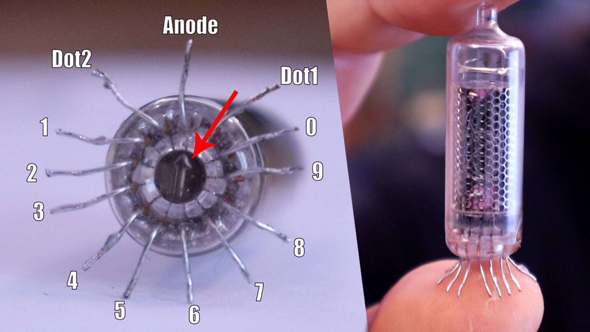
Control a nixie tube with Arduino and simple BJTs. In this tutorial I will demonstrate how to use a IN-16 (ИН-16) Soviet era tube, but any other tube with similar characteristics will work just fine: IN-14 (ИН-14) and IN-3 (ИН-3) for instance. Before you get started, you need to get acquainted with the Nixie tube. Each digit of the tube has an ending pin at the bottom of it. If any of these leads are connected to the ground, the digit will glow. Of course, that is provided the anode of the tube is supplied with ~170 to 180 volts. This “ignition voltage” differs for each tube but is generally in this range.
You can easily locate the anode of the tube, as it is generally situated at the back and on the bottom of the tube, it is usually marked with an arrow. A wide white structure reinforcement should be visible. This makes it very distinguishable from the other pins.
WARNING: Do not ever connect your tube between a high voltage source and the ground. 170V+ is very high voltage. Always connect a current limiting resistor between the anode and your power source. 20k is a good value for the IN-16. In any case, proceed with caution!
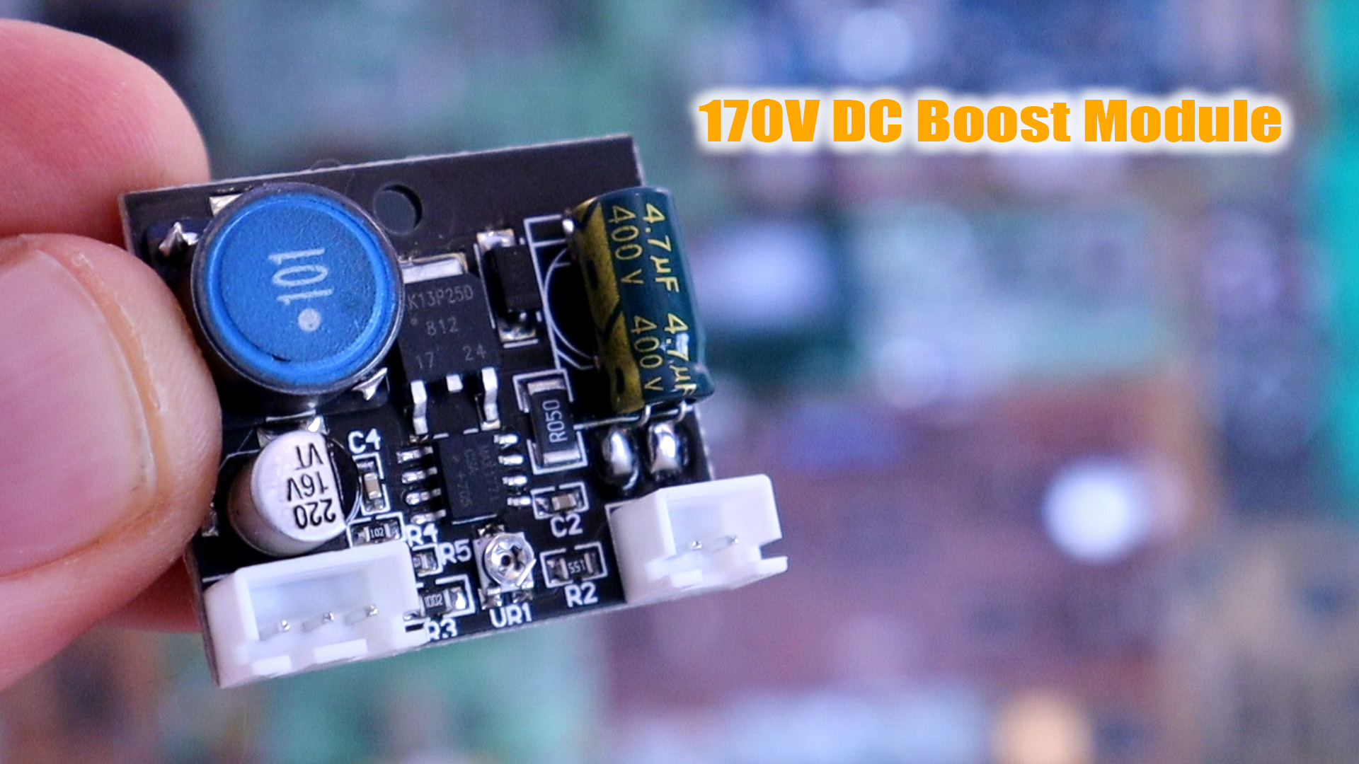
For high voltage I will use my a module taht could create 170V and you could buy it from eBay. It takes 5 to 15V as input and generates the 170V needed for the tubes. You can see how to make one and the schematic on this other tutorial here. Anyway, feel free to use a cheap eBay module, but if that’s the case I’d recommend using 12V as input. Low quality nixie power supplies may claim they work directly from 5V, but the reality is that often the power supply is pushed to its limit and would probably not last very long. For a single tube, a solid USB connector (5V / 500mA) is safe enough. If you plan on connecting any other tubes, you should use a bench power supply and gets a higher current, or use something beefier (5V / 2A for instance).
The transistors used in this tutorial need to have a Vce (Voltage Collector Emitter) above the 170V mark to be safe. In practice, 300V transistors are extremely common and so we will be used these. Numerous semiconductors companies produce them and they can be found under various names. The most common names are MPSA42 and KSP42. Cheap Chinese copies also exist since the design of this transistor is so ubiquitous.
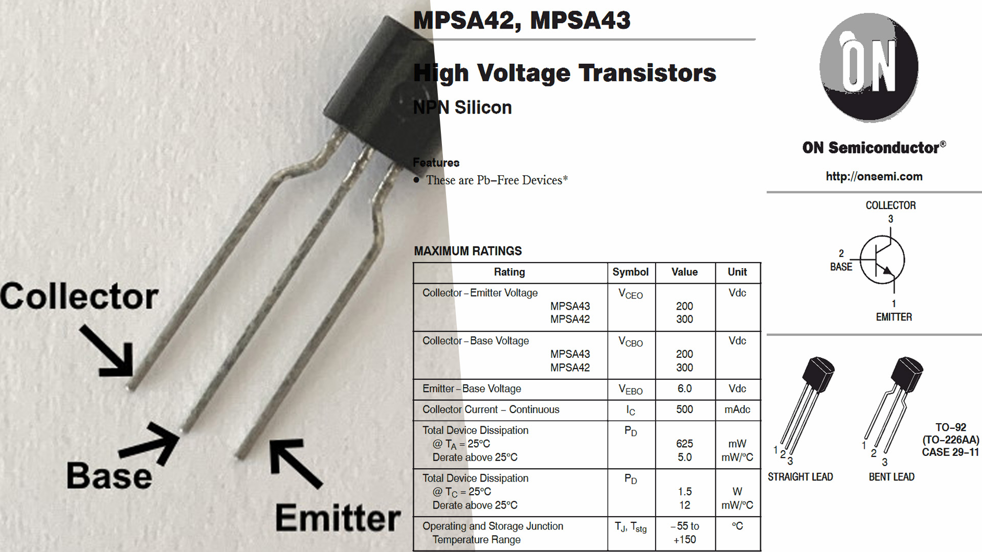
Just be careful of the pinout; depending if the transistor is facing you or not. To use these transistors, we simply ground the emitter, and connect the collector a tube’s digit lead (cathode). The arduino then controls the base. If the transistor is turned on, we effectively ground the cathode; which in turns light up the selected digit. It’s as simple as that!
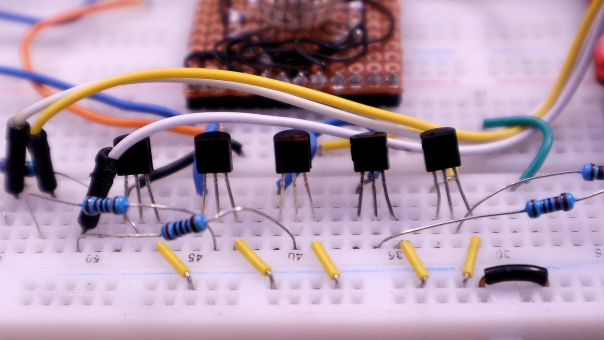
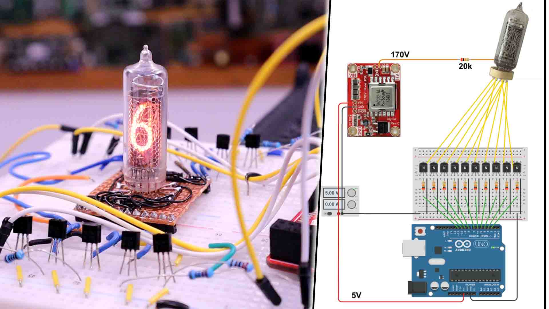
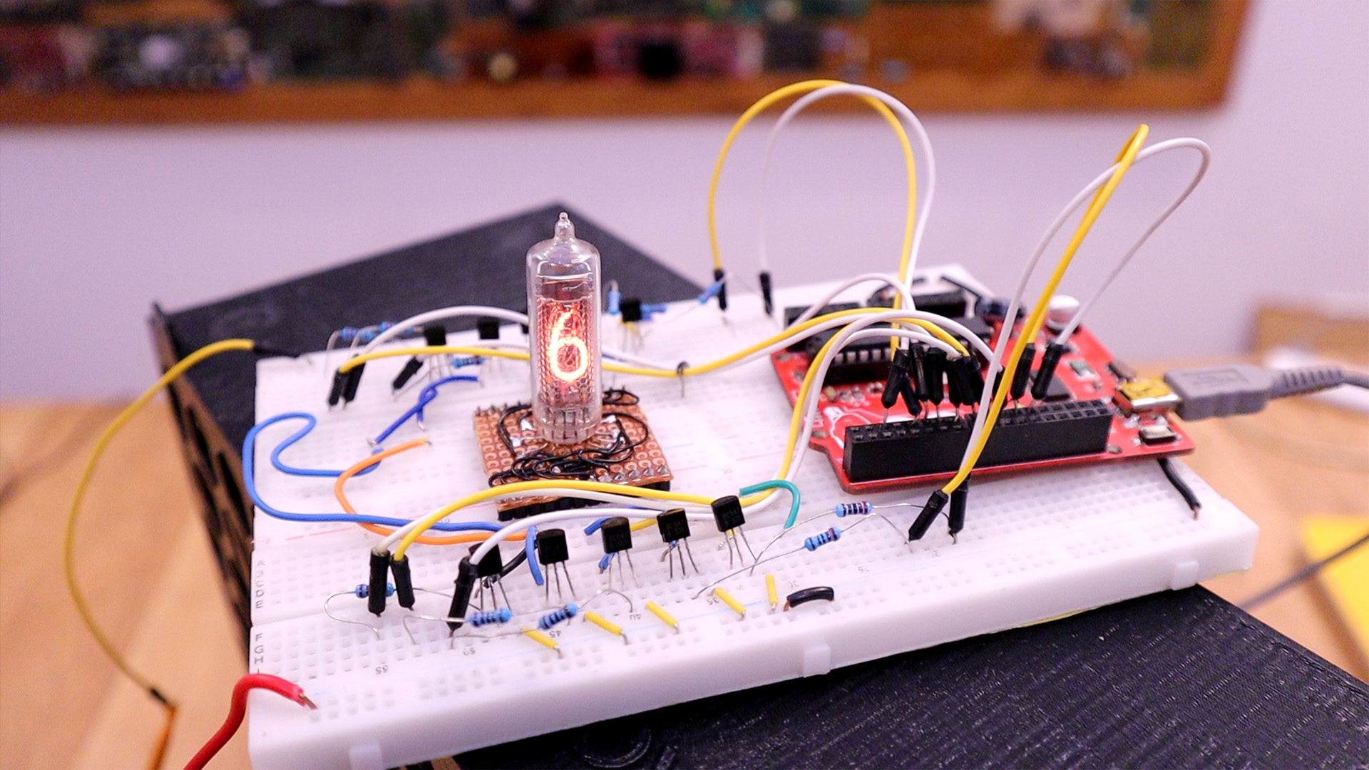
A lot of wiring is needed to make this work since we haev a lot of connections for each transistor. Key points:
- Don’t forget the 15 to 20k resistor between the high voltage and the tube’s anode.
- Connect Arduino pin 2 to the tube’s 0 digit, Arduino pin 3 to tube’s 1 digit, etc. etc. all the way to Arduino pin 11 matching the tube’s 9 digit.
- If using 5V, connect power source to “5V” on the Arduino
- If using 12V, connect power source to “Vin” on the Arduino
The code below is a simple counter from 0 to 9. At 0, we turn on pin 2 and turn off all other pins. At 1, we turn on pin 3 and turn off all other pins, etc. etc.
int nixie_pins[10]; //Array holding all our pins
//function that translates a 0-9 digit into which pin to turn on/off
void displayDigit(int digit){
  for(int i=0; i < 10; i++){
    if(i == digit){
      digitalWrite(nixie_pins[i], HIGH);
    }
    else{
      digitalWrite(nixie_pins[i], LOW);
    }
  }
}
void setup(){
  //Define all our pins as output and add them to array
  //This could be dramatically shortened with a for loop,
  //but this verbosity exposes in a simpler way what we
  //are achieving.
  pinMode(2, OUTPUT); nixie_pins[0] = 2;
  pinMode(3, OUTPUT); nixie_pins[1] = 3;
  pinMode(4, OUTPUT); nixie_pins[2] = 4;
  pinMode(5, OUTPUT); nixie_pins[3] = 5;
  pinMode(6, OUTPUT); nixie_pins[4] = 6;
  pinMode(7, OUTPUT); nixie_pins[5] = 7;
  pinMode(8, OUTPUT); nixie_pins[6] = 8;
  pinMode(9, OUTPUT); nixie_pins[7] = 9;
  pinMode(10, OUTPUT); nixie_pins[8] = 10;
  pinMode(11, OUTPUT); nixie_pins[9] = 11;
}
void loop(){
  //Count from 0 to 9
  for(int i=0; i < 10; i++){
    displayDigit(i);
    delay(500);
  }
}
That’s all there is to controlling a tube! Of course, since we need 10 IO for a single tube, it gets rapidly impractical. This is why the 74141 BCD decoder was invented: you reduce needed pins from 10 to 4. You can do even better though: by using 74595 bit shifters, you only need a 3 pin SPI connection to control as many pins as you need. This principle has been applied in my serial nixie driver design.
Make sure that you subscribe and if you consider supporting my work, check my PATREON page. Thanks again and see you alter guys.