Full tutorial on how to control the Arduino UNO ports using register. Port register manipulation, so be able to set pins as output/input with the DDRB, DDRC and DDRD registers, set pin to high or low PORTB, PORTC and PORD regsiters, or read inputs with the PINB, PINC or PIND registers. See the difference between using functions such as digitalWrite() and using directly the registers.
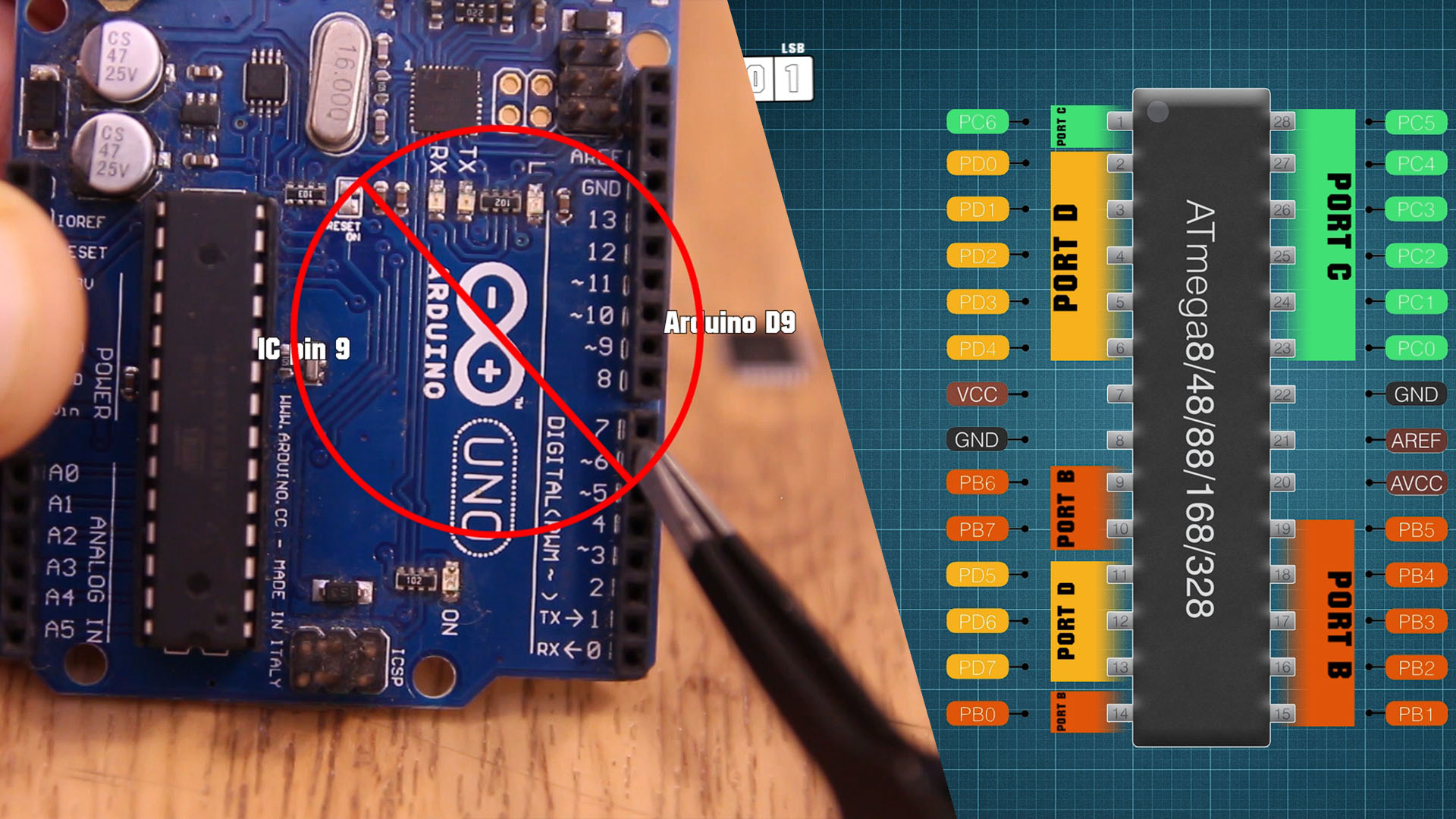
The Arduino UNO board is using the ATmega328p-PU microcontroller. This IC has 28 pins and it has a DIP package. Pins are labeled like below, starting from the dot on the first pin (top left corner), to pin 14 and then on the other side to pin 28. Now the connection between these pins and the pins of the real Arduino board is not using the same names. I mean pin 9 from the IC for example, is not connected to pin D9 from the board. As you can se below. pin9 of the chip coresponds to PB6 which port B6 and that is actually a crystal oscilaltor input pin. Another example, pin 4 of the chip, is not conencted to pin D4 of rthe Arduino UNO baord. Actually pin 4 of the chip represents PD2 which is connected to D2 pin of the Arduino board. You get the idea, right?
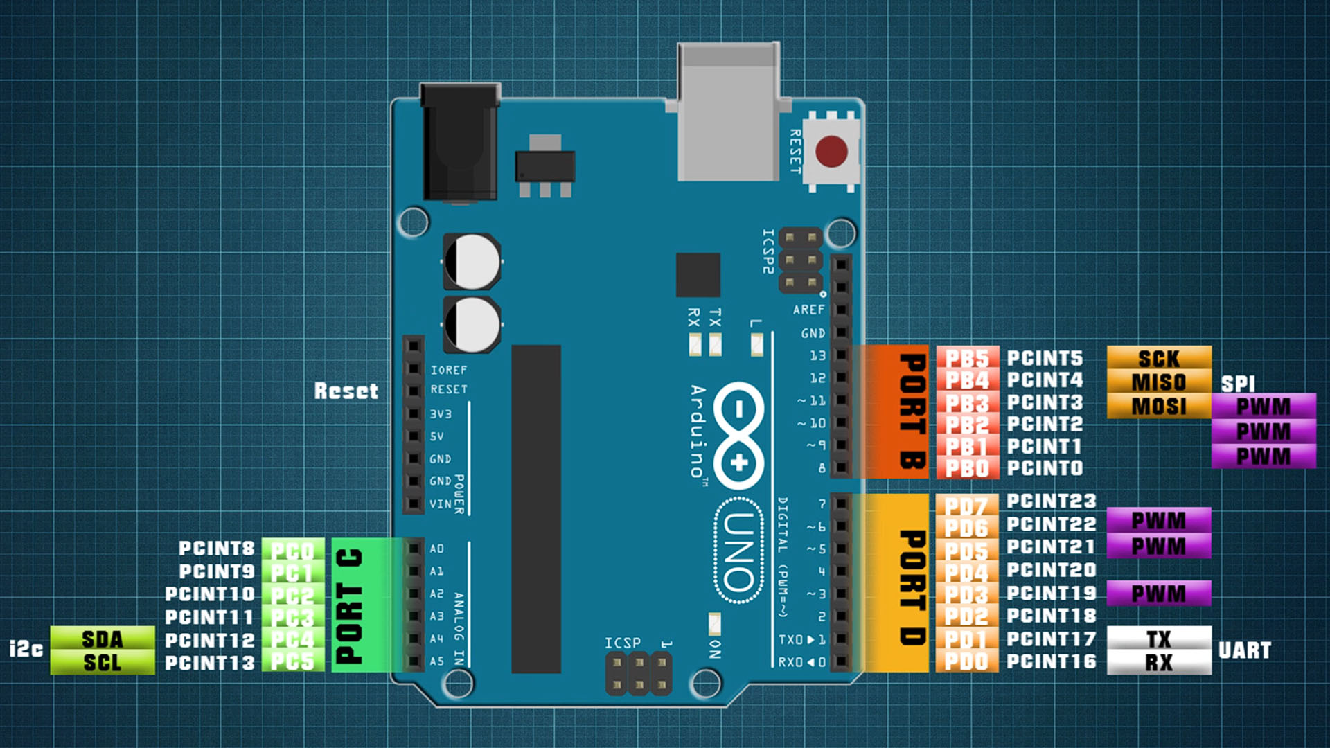
The Atmega328, which is the microcontroller the Arduino UNO is using, has 3 digital ports, port B, C and D. Each of this port is controlled by a register and since the Arduino UNO is an 8-bit board, each register could control 8 bits, so 8 pins. In this way, digital pins of the Arduino from D0 to D7 are controlled by port D register. Digital pins from D8 to D13 are controlled by port B. And the analog pins A0 to A5 are controlled by port C. Then each of the pins could have extra functions such as i2c communication pins, SPI communication, UART communication, PWM output, reset pin or the crystal oscillator input. So this below would be the final port map of the ATmega328 microcontroller where we have the port pins with one color and the real Arduino pins from the board with a different color in order to make you understand better.
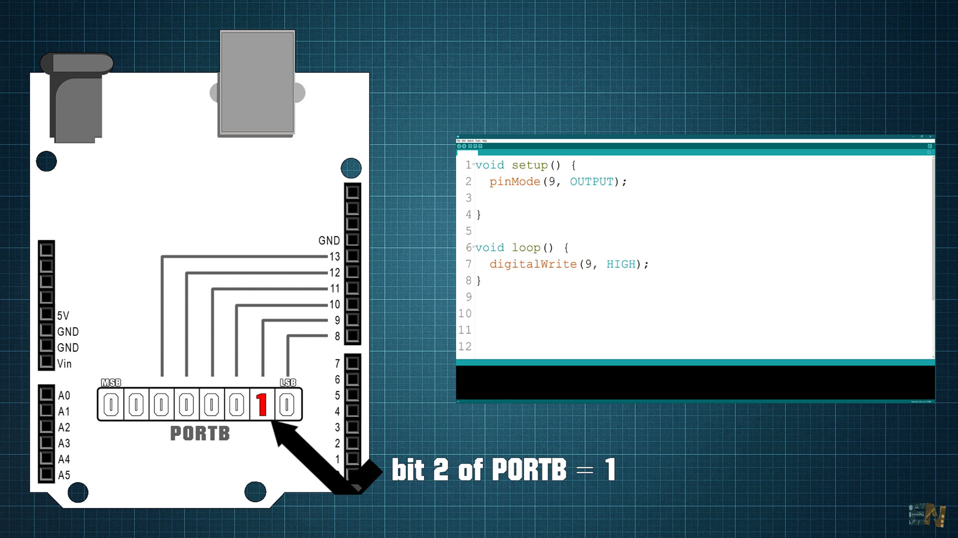
Ok, now let’s learn how to control these B, C and D ports. For example, you all know taht with digital write I could set digital pin D9 for example, to be high or low. But internally, what I really do is place a 1 on the second bit of the port B register. Why? Well, because that bit as you remember, represents digital pin 9 of the Arduino and by setting it to a 1, it means it set to HIGH. But
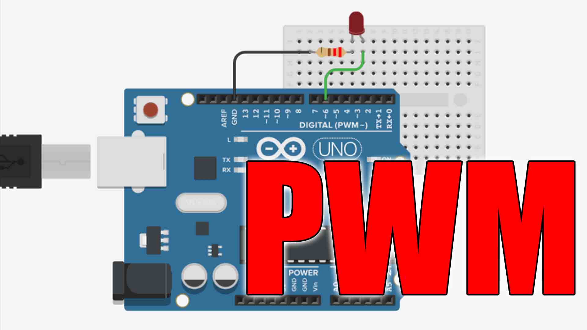
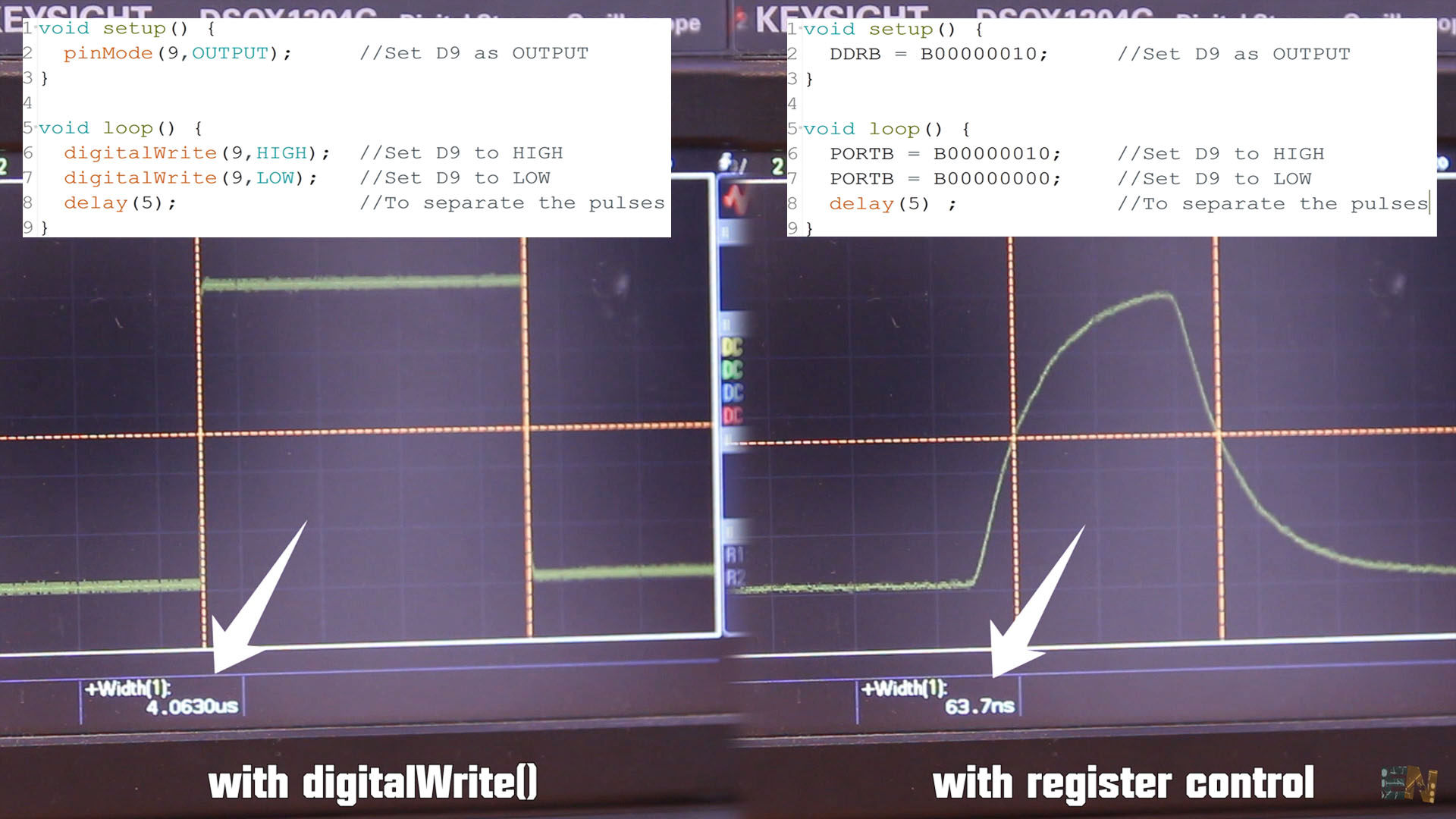
In an empty Arduino code, I set pin 9 as output. Then in the void loop, using digitalWrite(), I put that pin to HIGH and then with no delay in between I put the pin to LOW and then I place a delay of 5ms. The void loop will repeat itself over and over. This Arduino works at a speed of 16Mhz, and since there is no delay between the LOW and HIGH state of the pin, this code should create a very, very, short pulse. 1 second divided by 16Mhz is 62 nanoseconds. I upload this code to the Arduino and connect my oscilloscope to pin D9. Below you can see the signal. Each 5ms we have a short pulse but if I make a zoom in and I measure the width of this pulse, we can see it is 4 us. But why so long? There is no delay between HIGH and LOW so why isn’t this in the range of ns? Well, that’s because we are using digital write which is a function of Arduino and this takes a while to execute. I upload this second code using register control. I zoom in and now the pulse is a lot shorter. Now the pulse is only 64ns that is 60 times faster than before. The difference in time is amazing, so if your code needs a lot of speed, using register control is a lot faster. I now use port control for all my projects and the results are way better.
Ok, so remember that Arduino has 3 ports B, C and D. Today we center only on digital read and write so we won’t use analog values. In a normal code, if you want to set a pin to HIGH you first have to define it as an OUTPUT, right? For that we use the data direction register or DDR. We have DDRB, DDRC and DDRD for each port. Placing a 0 to these registers means the pin is input and with a 1 the pin is output. Let’s say you want to set pin D3 as output and the rest to inputs. For that we do DDRD, because pin D3 is on port D, and we equal this to this binary value (B00001000). As you can see the fort bit (bit3 because we start from 0) is equal to 1 so pin D3 will be an output. If you want for example pins D2 and D4 as output you would do something as below.
void setup() {
  DDRD = B00010100;         //Sets D2 and D4 as OUTPUT and the rest as INPUT (not recommended)
}

void loop() {
  //your code here...
}
But this is not a good way to configure registers. Why? Well because we affect all the bits of that register even if we only want to change one bit for one pin. In the example before, we wanted to set pin D2 and D4 as OUTPUT, so we equal DDRD to this value (B00010100). So, we set D2 and D4 as OUTPUT but we also set all the other pins as INPUT. What if we don’t want that. Imagine that pins 5 and 7 are already set as OUTPUT in a different part of the code and with the line of code above, you set those pins to as INPUT and you don’t want that. How to set only pin D2 and D4 without affecting the rest. For that we use Boolean operators AND and OR. We use the AND operator to place 0s. And we use the OR operator to place 1s.
void setup() {
  DDRD = B00010100;         //Sets D2 and D4 as OUTPUT and the rest as INPUT (not recommended)
  DDRD = DDRD | B00010100;  //This is safer as it sets ONLY pins D2 and D4 as OUTPUT

  //Other exampoles
  DDRB |= B00000101;        //Sets only D8 and D10 as OUTPUT
  DDRB &= B11100111;        //Sets only D11 and D12 as INPUT
  DDRC &= B11110110;        //Sets only A0 and A3 as INPUT
}

void loop() {
  //your code here...
}
So, for putting D2 and D4 to OUTPUT instead of making DDRD equal to the byte, we do DDRD "OR" equal to and the byte. An OR operator works like this. If we multiply 0 with 0 we get a 0. If we multiply a 1 with 1 we get a 1. If we multiply a 1 with 0 or a 0 with a 1 we still get 1. That’s why we use this operator to put 1s, because in any case there is a 1, the 1 will win. Only when both values are 0 the output is still 0.
But now let’s say you want to set to INPUT a pin so we have to put a 0. Let’s now put D5 to INPUT without affecting the rest. For that we use the AND operator. In this case, 1 AND 1 will give a 1. 1 AND 0, 0 AND 1 or 0 AND 0 will all give a 0 output. Only when both are 1 the output will be 1 that’s why we use this to place 0s. DDRD = DDRD &= B11011111; puts D5 as INPUT.
Ok so now we know how to set the pin to input or output. Let’s see how to set it to high or low. For that we use the PORT registers. We have once again, PORTB, PORTC and PORTD. Setting a bit to 1 means the pin is set to high and with a bit set to 0 means the pin is set to low. Ok, so before we have set pin D2 to be OUTPUT, now let’s set it to HIGH. For that we equal PORTD to this binary value (B00000100) where we put a 1 on to the third bit of the register which represents pin D2. Remember to use OR operator. To palce a pin to LOW we palce a 0, so we use AND operator.
void setup() {
  PORTD |= B00000100;         //Sets only D2 to HIGH

  PORTB &= B11111001;         //Sets only D9 and D10 to LOW
  PORTB |= B00110000;         //Sets only D12 and D13 to HIGH

  PORTC |= B00000010;         //Sets A1 to HIGH
}

void loop() {
  //your code here...
}
As you can see in the examples above, when we want to put "1s" we make the rest of the bit "0s" and when we want to put "0s" we make the rest of the byte to be "1s" so we won't change the rest of the bits, only the ones we want. But there is a simpler way, for example, instead of changing the byte from B00000100 to B11111011, we could use the "!" and invert the byte. For exaple !B00000100 is equal to B11111011. So putting a "!" before the byte, will invert all the bits. See the example below, where se set D2 to HIGH and LOW. When I set it to LOW I use the same byte but inverted with "!".
void setup() {
  DDRD = |= B00000100;  //Set only D2 as OUTPUT
}

void loop() {
  PORTD |= B00000100;         //Sets only D2 to HIGH
  delay(1000);
  PORTD &= !B00000100;        //Sets only D2 to LOW (we use ! to invertt the byte)
  delay(1000);
}
How can we read the value of a pin using registers instead of digitalRead().For that we use the PIN registers, PINB, PINC and PIND. This will store the input value of each pin for each port. Let’s say that you define pin D5 as input with this line of code below in the setup void. Now in the code you want to read pin D5 value. Pin D5 input is represented by the sixth bit of the PIND register so we have to check that. If you want to check if a pin is high we make a AND between the PIND register and a byte where the only 1 is on the sixth bit.
Have in mind that int value = PIND & B00100000; , when D5 input is high, it will equal "value" to B100000 which in digital is 32. When D5 input is LOW, "value" will be 0. So we make jumps from 0 to 32. If you want to make jumps from 0 to 1, you need to shift the bits as you can see below. If we check the fifth bit, we shift 5 to the right, if we check the third bit, 3 to the left and so on.
void setup() {
  DDRD = &= !B00100000;  //Set only D5 as INPUT
}

void loop() {
  //This is NOT equal to: int value = digitalRead(5);
  //Why? Because value = an 8 bit value. For only 1 bit, you need to shif regisers
  int value = PIND & B00100000;


  //This is equal to  int value2 = digitalRead(5);
  //Since we read the fifth bit, we need to shift 5 times to the right
  int value2 = (PIND >> 5 & B00100000 >> 5);

  //In case you want to make an if decision you don't have to shift
  //Next line equal to: if(digitalRead(5))
  if(PIND & B00100000){
    //Add your code...
  }

  //We can invert the result: Next line equal to: if(!digitalRead(5))
  if!(PIND & B00100000){
    //Add your code...
  }
}
So guys, that’s how we make digital read and write or set the pin to INPUT or OUTPUT with register control. Make sure you watch my previous Arduino101 video. Read the datasheet. Make sure that you subscribe and if you consider supporting my work, check my PATREON page. Thanks again and see you alter guys.