Full tutorial on how to control the Arduino UNO pin change interruption ISR. We will see the registers we need to set before, what are the ISR vectors and how to execute interruptions. This, for example, will allow us to have interruptions in all the pins in boards based on the Atmega328P. But wait, Arduinos have only 2 interrupt pins, right? Well, no. Those are hardware interruption pins. We are nos talcking about the PCINT pins. In this post we will see what Pin Change interrupts (PCINT) are and how they work, interruptions different from the normal interruptions (INT) we are used to.
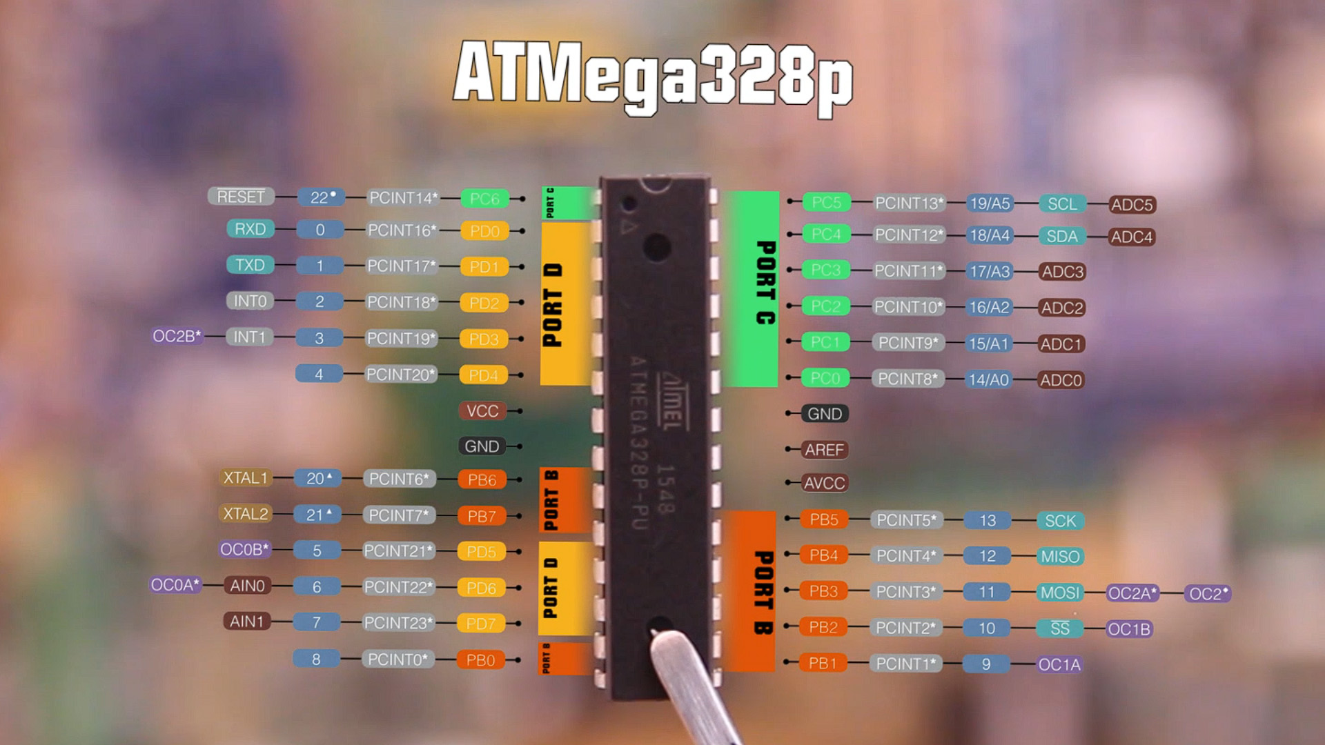
The Arduino UNO board is using the ATmega328p-PU microcontroller. This IC has 28 pins and it has a DIP package. But the pins of the IC are not labeled the same as the pins of the Arduino UNO Board. For example pin D13 of the Arduino is connected to pin 19 of the Atmega328p chip. Anyway, each of the digital pins are related to a port and we have 3: PortB, PortC and PortD. Each port is controlled by 8-bit registers so each port could control 8 digital pins, that's why each pin is labeled belos as PB0 to PB7 as for Port B 0 to Port B 7. Also, as you can see below, each of this digital pins has also related a diferent label named PCINT and this goes from, PCINT1 to PCINT23. So remember that each digital pin will have associated a PCINT bit. But, what is this PCINT?
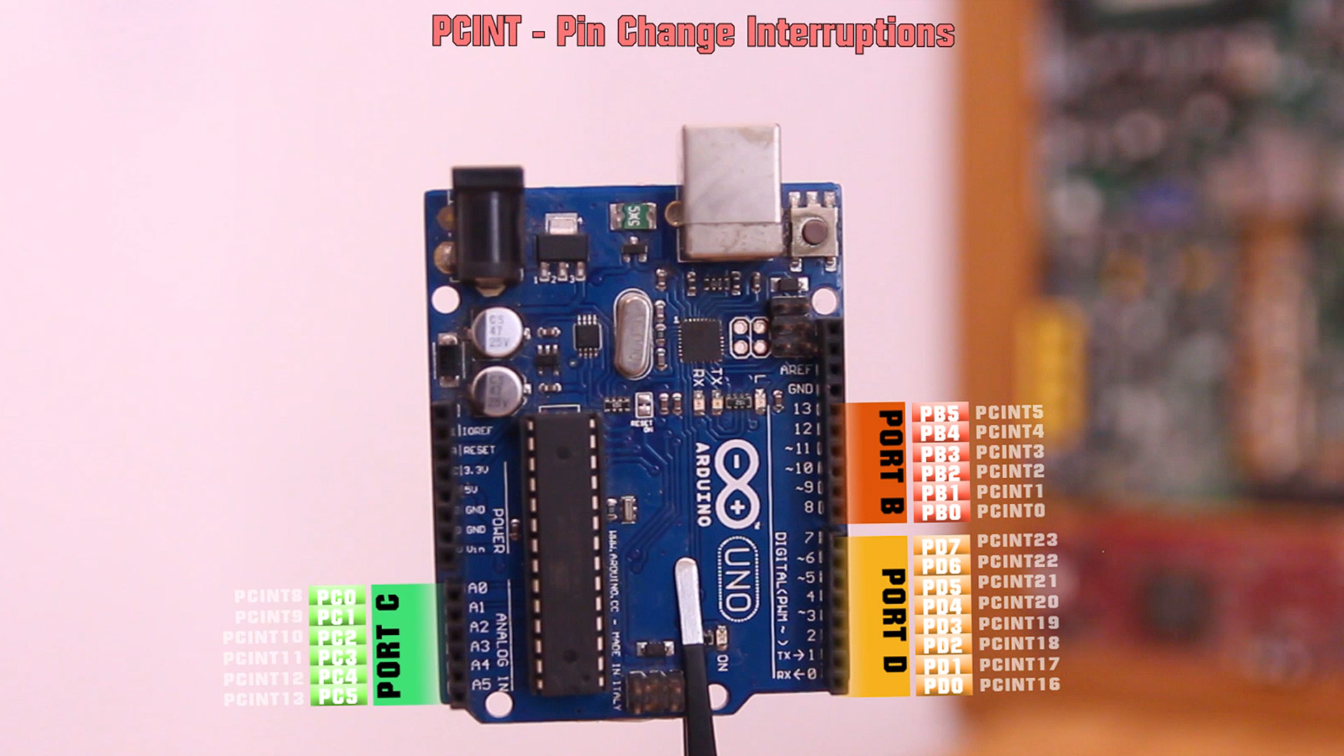
With Arduino we have two types of interruptions, the INT for external hardware interruption and the PCINT for pin change interrupt. Today we will take a look at these last ones, the pin change interruptions and we leave the hardware interruptions for a future tutorial. Hardware interruptions are very limited, for example on the Arduino UNO, only pins 2 and 3 could trigger a hardware interruption. On the other hand, the PCINT interruptions don’t act over just one pin, but over a group of pins better known as a port. So, remember from the last tutorial that the Arduino UNO is using the ATmega328 microcontroller and as you remember this below was its pinout and we had 3 ports, the port B, C and D. We have several registers that control the interruptions of these ports. PCINT also have some disadvantages compared to the usual INT.
Second, unlike INT interrupts that allow you to configure the CHANGE, FALLING, RISING, LOW, and HIGH trigger, INT interrupts only distinguish CHANGE events. And finally, for this reasons, they are slightly slower than INT interrupts. But in general it is not something that should worry us, it is an irrelevant difference except in very extreme cases.
You should already know that the Arduino code is sequential, running in series meaning that till one instruction is not over, we can’t execute the next interruption. For example, in the code below we run 3 functions (1, 2 and 3) and we read some inputs from some buttons. The first reads the temperature from a thermocouple. The second function calculates some PID values and the third function apply the PID result to some analog outputs to control a heater. Between the functions we read the state of two pins connected to some push buttons. Since the Arduino code is sequential, is obvious that function 2 won’t run till function 1 is not over, and function 3 won’t run till function 1 and 2 are over. Even more, if we press the push button while function 1 is still running, with the lines of code below, we won’t detect that the button was pressed, because the digital read won’t run till function 1 and 2 are done. So how could we change a variable used in function 3 for example, while we are still running function 1. For that we use interruptions.
When an interruption is triggered, this will pause the code in that exact moment and take it to the interruption vector. Here we run the code of the interruption, which could be anything, and when this is over, we get back to the code and keep going from that same exact moment. With PCINT, if activated, each time an INPUT changes its value, from HIGH to LOW or from LOW to HIGH, an interruption will be triggered.
There are several registers involved in the activation and use of pin change interrupts . We are going to see the process step by step, using the Atmega 328p as a reference as it is the most used in Arduino Uno and Nano. First, let's see how to enable or disable PCINT for each pin.
In the first place, we can activate or deactivate the PCINT associated to a group of pins with the PCICR (Pin Change Interrupt Control Register) register. Here we have 3 bits, which control the activation or deactivation of the PCINTs for each group of pins. We use the first 3 bits of this register where bit 0 is for PCIE0, bit 1 is for PCIE1 and bit 2 is for PCIE2.
| Bit 7 | Bit 6 | Bit 5 | Bit 4 | Bit 3 | Bit 2 | Bit 1 | Bit 0 |
| PCIE2 | PCIE1 | PCIE0 |
void setup() {
  PCICR |= B00000100;			//Bit2 = 1 -> "PCIE2" enabeled (PCINT16 to PCINT23)
}

void loop() {
  //your code here...
}
These PCIE bits represent the pin change interrupt enable bit, so if we set the bit to 1, interruptions for that group are activated, if we set it to 0, well, interruptions are disabled. PCIE0 controls the group of pins for PCINT0 to PCINT7. If we take a look at the Arduino port map, we can see that those interruptions pins are connected to pins from digital pin D8 to D13 which are bits 0 to 5 of port B. PCIE1 controls the group of pins for PCINT8 to PCINT14 and those correspond to the analog pins of the Arduino A0 to A5. Finally, PCIE2 controls the group of pins for PCINT16 to PCINT23 and these correspond to digital pins of the Arduino D0 to D7.
Once the PCINT is activated for a group of pins, we must say which pins of that group can trigger the interrupt. For that we have the registers PCMSK0, PCMSK1 and PCMSK2 (Pin Change Mask), in which each bit indicates whether or not the pin triggers the PCINT. Now setting a PCINT bit to a 1, it means that pin will trigger interruption. Setting it to a 0, it means the pin won’t trigger interruption on pin change. below you have the registers and bits of each in order to select any of the PCINT bits. See also the code example below.
| BIT | Bit 7 | Bit 6 | Bit 5 | Bit 4 | Bit 3 | Bit 2 | Bit 1 | Bit 0 |
| PCINT | PCINT7 | PCINT6 | PCINT5 | PCINT4 | PCINT3 | PCINT2 | PCINT1 | PCINT0 |
| Arduino Pin | Cristal2 | Cristal1 | D13 | D12 | D11 | D10 | D9 | D8 |
| BIT | Bit 7 | Bit 6 | Bit 5 | Bit 4 | Bit 3 | Bit 2 | Bit 1 | Bit 0 |
| PCINT | - | PCINT14 | PCINT13 | PCINT12 | PCINT11 | PCINT10 | PCINT9 | PCINT8 |
| Arduino Pin | - | Reset | A5 | A4 | A3 | A2 | A1 | A0 |
| BIT | Bit 7 | Bit 6 | Bit 5 | Bit 4 | Bit 3 | Bit 2 | Bit 1 | Bit 0 |
| PCINT | PCINT23 | PCINT22 | PCINT21 | PCINT20 | PCINT19 | PCINT18 | PCINT17 | PCINT16 |
| Arduino Pin | D7 | D6 | D5 | D4 | D3 | D2 | D1 | D0 |
Ok, as you can see below, first, as in the example before we activate PCINT for group PCIE2 with the first line of code. But then with the second line of code we make digital pin D5 to be able to trigger interrupt. We set bit 5 of the PCMSK2 register to a 1, so PCINT21 is enabled and that represents digital pin D5 as you can see in the tables above.
void setup() {
  PCICR |= B00000100;			//Bit2 = 1 -> "PCIE2" enabeled (PCINT16 to PCINT23)
  PCMSK2 |= B00100000;			//Bit5 = 1 -> "PCINT21" enabeled -> D5 will trigger interrupt
}

void loop() {
  //your code here...
}
On the other hand, we have the PCIFR (Pin Change Interrupt Flag Register) register. The bits of this register are activated each time a change occurs in a pin of the group. To reset bhis flag, we have to put a '1' in the corresponding register. The flags are automatically reset when the associated ISR is triggered. So, for example if D5 triggers an interruption, the flag for PCIF2 will trun 0 because pin D5 is from PCMSK2.
| BIT | Bit 7 | Bit 6 | Bit 5 | Bit 4 | Bit 3 | Bit 2 | Bit 1 | Bit 0 |
| PCINT | - | - | - | - | - | PCIF2 | PCIF1 | PCIF0 |
| Arduino PORT | - | - | - | - | - | PORT B | PORT C | PORT D |
Ok so at this moment we know how to set pins to be able to trigger interruptions. But as you remember, when the interruption is triggered, we pause the main code and we jump to the interruption vector where we execute the code for that interruption. So what is this interruption vector. Well, each of the 3 groups of pins has a ISR or Interrupt Service Routine. This is a loop in the code that when the interruption flag is triggered it will execute. For that, in the code we define the ISR and then we add the vector. We have 3 vectors, PCINT0 vect for pins from D8 to D13, PCINT1 vect for pins from A0 to A5 and PCINT2 vect for pins from D0 to D7.
• ISR (PCINT0_vect) for pin group D8 to D13
• ISR (PCINT1_vect) for pin group A0 to A5
• ISR (PCINT2_vect) for pin group D0 to D7
We now have all the elements that we need to explain how pin change interrupts work. To sum it all uo, in the example before, we have set digital pin D5 to trigger interruption. So we have to add the code for the PCINT2_vect ISR. So in the code, after or before the void loop, we add the lines below. This it the interruption loop for port D. Between the brackets we add our interruption code. Once these lines are executed, the interruption flag goes back to "1" and these lines of code won’t run again till another interruption of pin D5 is triggered.
ISR (PCINT2_vect)
{
    // For PCINT of pins D0 a D7
}
We want pin D5 to trigger interruption on pin change. In the code below, with the first line in the void setup, we enable PCIE2 because D5 corresponds to that group. With the second line we indicate taht PCINT21 will trigger interrupt because D5 is represented by taht group. Everything is set bwe we need to define the ISR vector. To pin D5 which is from port D, the ISR that corresponds is vector 2. That why we define the ISR PCINT2_vect. Between these brackets we define the code of our interruption.
void setup() {
  PCICR |= B00000100;			//Bit2 = 1 -> "PCIE2" enabeled (PCINT16 to PCINT23)
  PCMSK2 |= B00100000;			//Bit5 = 1 -> "PCINT21" enabeled -> D5 will trigger interrupt
}

void loop() {
  //your code here...
}

ISR (PCINT2_vect)
{
    // For PCINT of pins D0 a D7
}
Ok, now some things to have in mind. If you set for example pins 4 and 5, which are from the same port, to trigger interruptions, without consulting which pin created the interruption, you can’t possibly know which one of the two pins triggered the ISR. If pin 4 made the interruption we jump to the ISR of vector 2. If pin 5 made the interruption, we also jump to ISR of vector 2. That’s why when using PC interruptions of the same port, we must always consult which pin changed its value. To detect that we must store the previous value using a global variable and compare that each time. We should do the same if we want to detect rising or falling edges of an input. Knowing the previous and actual state of a pin, we can detect when it passed from high to low or from low to high.
bool D4_state = LOW;
bool D5_state = LOW;

void setup() {
  PCICR |= B00000100;			//Bit2 = 1 -> "PCIE2" enabeled (PCINT16 to PCINT23)
  PCMSK2 |= B00110000;			//D4 and D5 will trigger interrupt
}

void loop() {
  //your code here...
}

ISR (PCINT2_vect)
{
   if(digitalRead(4) && D4_state){
   	D4_state = HIGH;
	//Pin D4 triggered the ISR
   }
   else if(digitalRead(4) && !D4_state){
   	D4_state = LOW;
   }


   if(digitalRead(5) && D5_state){
   	D5_state = HIGH;
	//Pin D5 triggered the ISR
   }
   else if(digitalRead(5) && !D5_state){
   	D5_state = LOW;
   }
}
Another thing to have in mind. When we are inside an interruption, the rest of interruptions are on pause. That means if one pins triggers an interruption and in just a few moments a different pin triggers another interruption while we are still running the first interruption routine, the second interruption won’t trigger.
In conclusion, we must make the ISR routine as fast as possible. So what I recommend you is to just change values of variables in the ISR routine and then, let all the rest of calculations, decisions and so on, to be made in the void loop. In this way, the interruption is as fast as possible. On the same reason, if an interruption is too long, remember that during interruption, the rest of the code is on pause. So what if you are controlling the position of a step motor. If the interruption is too long, maybe the motor reached the end of its track but you can’t stop its rotation yet till the interruption is not over, so that will result into something bad.
Another thing, during the execution of an interrupt, Arduino does not update the value of the millis and micros function. So, the execution time of the ISR is not counted and the Arduino has a time lag. You can use the millis and micros function to count time between two interrupts. But during the interruption the time is not updated. What I want to say is that you can use for example, the millis function inside the ISR. But its value will be the value it had the time the interruption was triggered. As a consequence, the delay function does not work, because it bases its operation on the millis function. The micros function updates its value within an ISR, but it will start giving inaccurate time measurements past the 500us range. As a result, the delayMicroseconds function works in that time range, although we should avoid its use because we should not introduce delays within an ISR.
So now you know how to setup pin change interruptions. Please see all examples on this post for more details and check the datasheet of the ATmega chip. Stay tuned for more Arduino 101 videos soon. I hope that you have learned something new. If so, maybe give a like the video below and consider subscribing. If my videos help you, consider supporting my work on my PATREON or a donation on my PayPal. Thanks again and see you later guys.