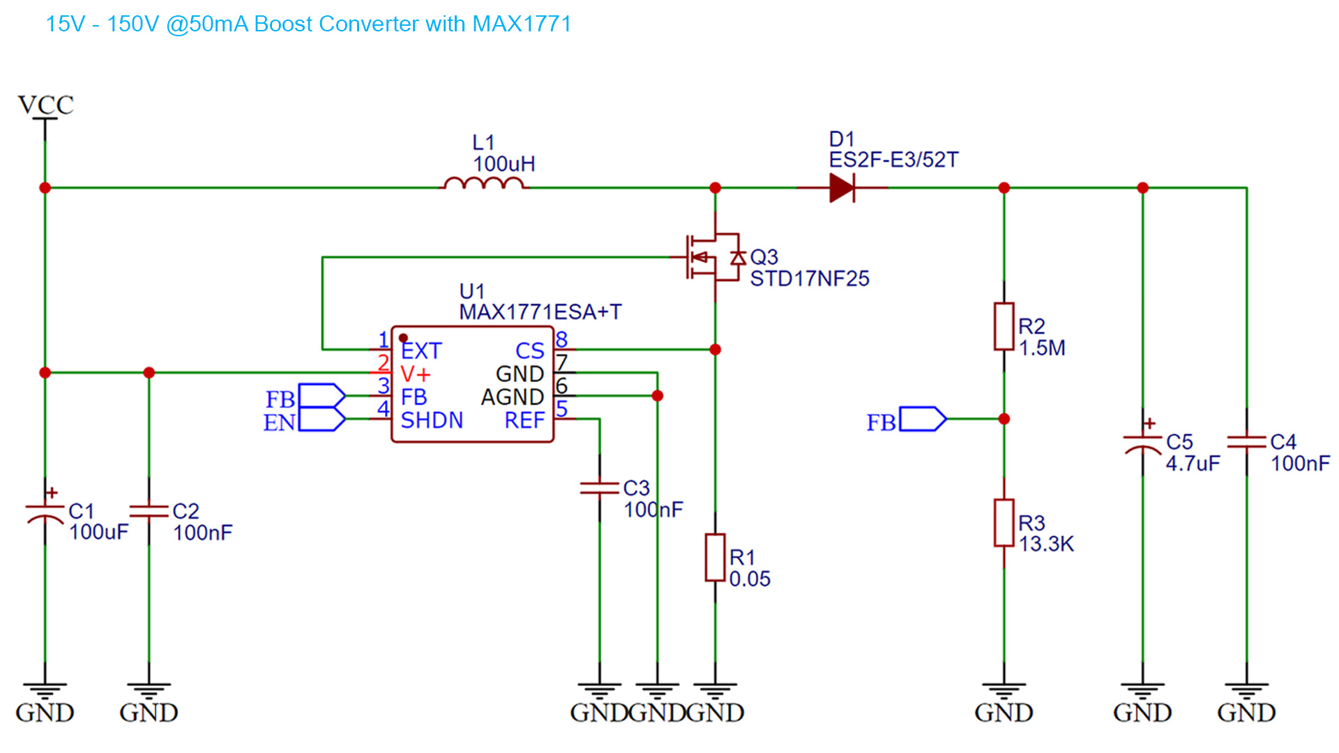
In this tutorial I'll show you the circuit of a basic boost converter for high voltage up to 170V with the MAX1771 driver. This is a boost driver that will apply a PWM signal to the a MOSFET and by that control the output voltage. The rest of the circuit is as a basic boost converter with a coil, diode and capacitor at the output.
Below you have all the parts needed for this circuit. Select the size you need for your PCB. Make sure the output capacitors are high voltage. Read more below in the tutorial.
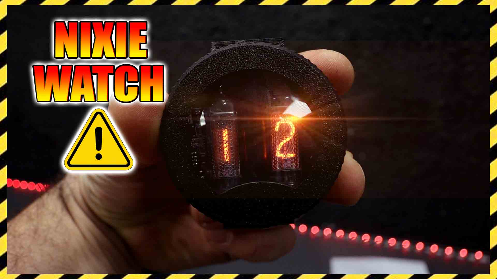
This circuit should be high efficency (around 85%) and output 50mA current. It should boost the voltage up to bewteen 150V and 220V and could be used as a Nixie Tube supply since those don't require much current. To get good resutls consider:
- Transistor Q3 is selected for low Qg, RDson and Coss
- Output capacitors C5 and C4 must be raterd for high votlage >250V
- D1 should be ultra-fast (<50ns) recovery, 1A and 220V
- C1 and C2 should be very close to pin 2 of the MAX1771 (Vcc)
- L1 should be 2A rated for 50mA output or 1A for 25mA output.
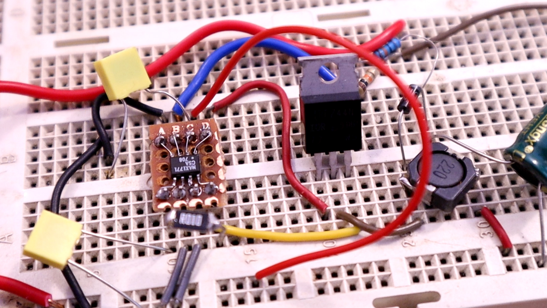
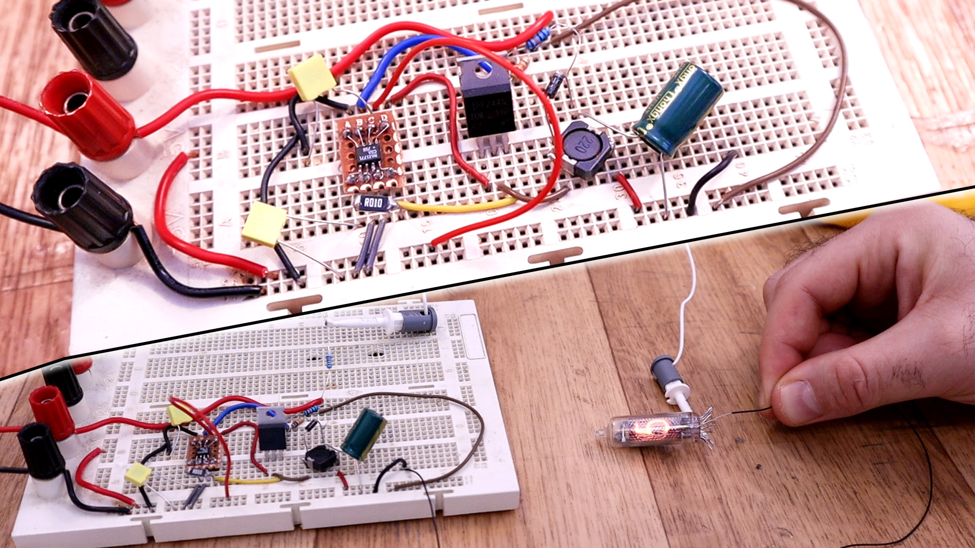
I've connected everything on the breadboard. I've used a different MOSFET than the one on the schematic but it works as well. It has to be N-Channel and >250V. The output capacitor must be for high voltage, otherwise itw ill blow. I've soldered the MAX1771 on a tiny PCB so I could use it on the breadbaord. Dureing tests, I've supplied the circuit with voltage from 3V to 12V. The output was always above 150V and taht's enough for my small nixie tubes. So is nice that even with 3V input, the output is above 150V.
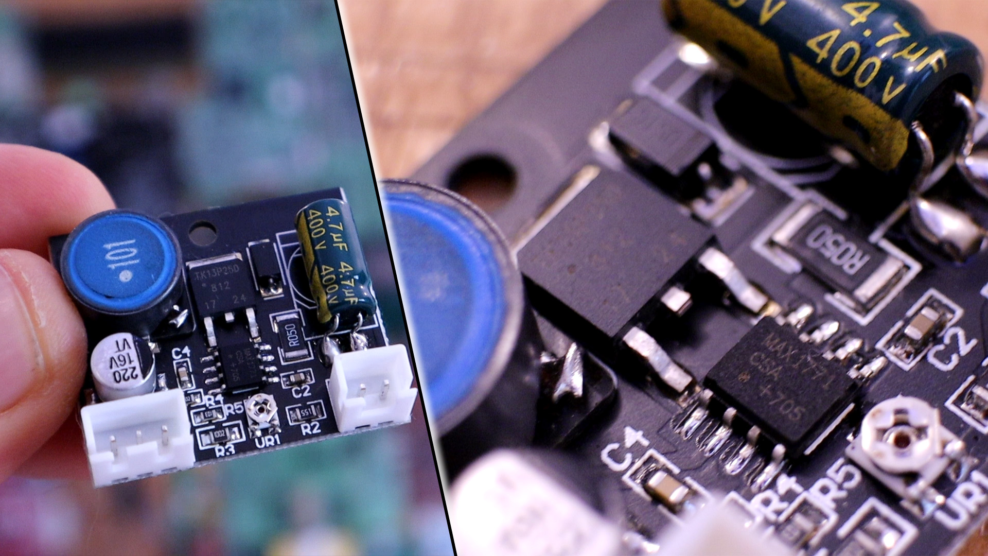
If you don't want to make your own circuit, you can always buy this module HERE that has the same circuit but with a potentiometer integrated in case you want to change the output voltage. For a few dolalrs you can have the module from eBay but if you want a smaller PCB you will have to make your own circuit. The module ahs input for Vcc (9-12V) and GND and EN pin for putting the module in shoutdown mode (SHDN HIGH) ow normal operation (SHDN LOW).