In this final part we merge all we know about Nexion display in just one platform, the front panel of a power supply and also comunicate with the Arduino and get/send data to it. This is part of a future project where I'll build a homemade varaiable digital pwoer supply.
This is just a test. Instead of the real voltage and current read from the future powere supply, I will use two potnetiometers for tests. So, first of all, for this first example we need the schematic below. But only make the connections after we uplaod the code since the display uses the RX and TX pins and if something is connected to those pins, we can't uplaod the code. But we need the Arduino code part but also the Nextion TFT interface. For that we will use Nextion editor and create our interface.

Downlaod from below the Nextion editor software and install it. Then run the aplication and create a new file. Add all the buttons/pages/labels from the toolbox. Downlaod the final TFT file from below and uplaod it to the display.
To uplaod the TFT file we have to compile the project. If we have no errors in the console, we go to File and select open build folder anc copy the tft file. Insert a micro SD card into your PC and copy the tft file there. The SD card must be empty and formated to a fat32 format.
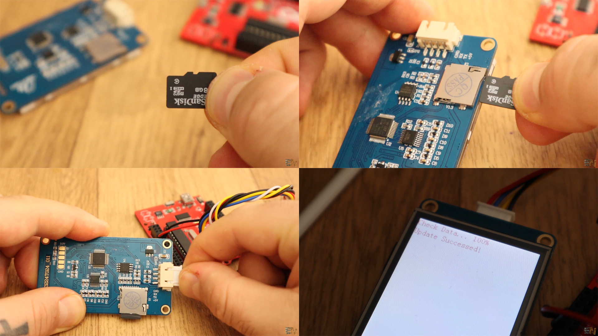
Now that the tft file is on the SD card make sure the Nextion display is not powered on. Insert the SD card into the card slot. Now power up the display with 5V. You will see on the screen that the new tft interface is being uploaded. Once you see 100%, power off the display and remove the SD card. Now power back the display and connect the TX and RX pins as in the schematic the two potentiometers to A0 and A1 for tests.
Copy the code from below or just download it. Upload the code to the arduino before you connect the TX and RX pins. After you uplaod the code, connect the UART TX and RX pins and power up the Arduino and display. Add the potentiometers. As you can see in the code we read the analog values and send those to the screen for the voltage and current labels but also for thw wave. Uplaod the code and test it.
//Inputs/outputs
int Volt_in = A0;
int Curr_in = A1;


float Volt_set = 0;             //Variables for the ones voltage values
float Volt_ten_set = 0;         //Variables for the tenths voltage values
float Volt_hun_set = 0;         //Variables for the hundredths voltage values
float Curr_set = 0;             //Variables for the ones current values
float Curr_ten_set = 0;         //Variables for the tenths current values
float Curr_hun_set = 0;         //Variables for the hundredths current values

float Voltage_set = 0.0;        //Here we save the final voltage value (teh sum of all 3 votage variables above)
float Current_set = 0.0;        //Here we save the final current value (teh sum of all 3 current variables above)

int Real_Voltage = 0;           //Variable for the real read of the voltage output
int Real_Current = 0;           //Variable for the real read of the current value
int Real_Power = 0;             //The power will be current*voltage

bool output_enabeled = false;   //This will show if the output is enabeled or not

void setup() {
 pinMode(Volt_in,INPUT);
 pinMode(Curr_in,INPUT);
 Serial.begin(9600);          //Default baud rate of the Nexion TFT is 9600!
 /*Uncomment and delete this line if you want to change baud rate to 115200
 Serial.print("bauds=115200");
 Serial.write(0xff);
 Serial.write(0xff);
 Serial.write(0xff);*/
 Serial.print("cle 5,255");   //Send instruction to clear the waveform
 Serial.write(0xff);
 Serial.write(0xff);
 Serial.write(0xff);
}


void loop() {

  if(Serial.available()>0)
  {
    String Received  = Serial.readString();     //get the received string from the display
    //Serial.println(Received);

    if(Received[0] == 'b')                      /*In the display code, when the back button is pressed I send all the variables
    But first I send the "b" character. That's why, when we detect a "b", then we store each forth character as a float value.
    why each forth? because after each sent value, the uartt will write 3 full bytes as seen before*/
    {
      Volt_set = float(Received[1]);        //First, than the 5th, than the 9th etc...
      Volt_ten_set = float(Received[5]);
      Volt_hun_set = float(Received[9]);

      Curr_set = float(Received[13]);
      Curr_ten_set = float(Received[17]);
      Curr_hun_set = float(Received[21]);

      Voltage_set = Volt_set + (Volt_ten_set/10) + (Volt_hun_set/100);      //We summ all parts to get the total set voltage value
      Current_set = Curr_set + (Curr_ten_set/10) + (Curr_hun_set/100);      //We summ all parts to get the total set current value

      //Serial.print(Voltage_set); Serial.print("   "); Serial.println(Current_set);    //Uncomment this for serial debug
    }

    if(Received[1] == 'f')                //if we receive an f, then the output will turn off
    {
      output_enabeled = false;
      Serial.print("Output: ");
      Serial.println(output_enabeled);
    }

     if(Received[1] == 'n')               //if we receive an n, then the output will turn on
    {
      output_enabeled = true;
      Serial.print("Output: ");
      Serial.println(output_enabeled);
    }
  }//end of if serial


 Real_Voltage = map(analogRead(Volt_in),0,1024,0,3200);     /*Read the values of the potentiometers and map the output to 0 to 3200
 In the display code in the timer, we divide 3200 in such a way that we het 32,00 volts. */
 Real_Current = map(analogRead(Curr_in),0,1024,0,300);      //Read the values of the potentiometers
 Real_Power = Real_Voltage/100*Real_Current;                //Get the power

 Serial.print("Real_Voltage.val="); //The variable we will change on nthe screen, in this case the voltage value
 Serial.print(Real_Voltage);        //Send the voltage value
 Serial.write(0xff);
 Serial.write(0xff);
 Serial.write(0xff);
 Serial.print("Real_Current.val="); //The variable we will change on nthe screen, in this case the current value
 Serial.print(Real_Current);        //Send the current value
 Serial.write(0xff);
 Serial.write(0xff);
 Serial.write(0xff);
 Serial.print("Real_Power.val="); //The variable we will change on nthe screen, in this case the power value
 Serial.print(Real_Power);        //Send the power value
 Serial.write(0xff);
 Serial.write(0xff);
 Serial.write(0xff);

 value_to_waveform(Real_Voltage/13); //use this function to send data to the waveform


}


//function that sends data to the waveform
void value_to_waveform(int val_wave)
{
  String Tosend = "add ";
  Tosend += 2;
  Tosend += ",";
  Tosend += 0;
  Tosend += ",";
  Tosend += val_wave;
  Serial.print(Tosend);
  Serial.write(0xff);
  Serial.write(0xff);
  Serial.write(0xff);

}
The code is a bit long but that's because we cant use FLOAT format with the Nextion display. That's why I multiply the voltage value by 1000 to get rid of the comma. Than I send taht to the screen in an INT format and I will divide tat value inside the display code. The code works. Stay tuned for updates and consider helping me on PATREON.