Brushed motors Arduino drone
Part 1 - Prototype PCB

INTRO
What's up my friends. In a past tutorial we have buid an Arduino based drone using brushless motors. That was a good project. But, uisng brushless motors could get the prject quite expensiv around 8$ for each motor and also for each ESC, so that could get you up to 80$ just for the motors. A cheapper solution is using mini brushed coreless motors and that's what we will do in this tutorial.
To control the DC brushed motors, we will only need a MOSFET for each motor, controlled with PWM signal. The input will be 3.7V from a lipo battery. The PID will be generated using data from and IMU module and the radio receiver will be a NRF24 module once again. So the transmitter will be the same as in the past TRANSMITTER tutorial so make sure you check that out in order to see how to build the transmitter.
Step 1 Part list
Ok so first of all we will see all the parts we need for this project and why we need each part. There are two ways to make this project. One is using an Arduino pro mini pn a drilled prototyping PCB and all the components or design our own PCB and have it printed by a professional manufacturer.
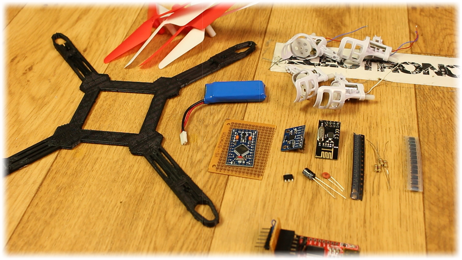
Full part list here
Step 2 The schematic
Ok, so we will use the Arduino pro mini of 5V and 16MHz. The input voltage will be 3.7V from the small lipo which will be enough since Arduino will also work at that voltage. To smooth the input voltage we add a capacitor at the input. To control the motors I'll use some MOSFETs. Remember to add the diode at each DC motor output to prevent MOSFET damage.
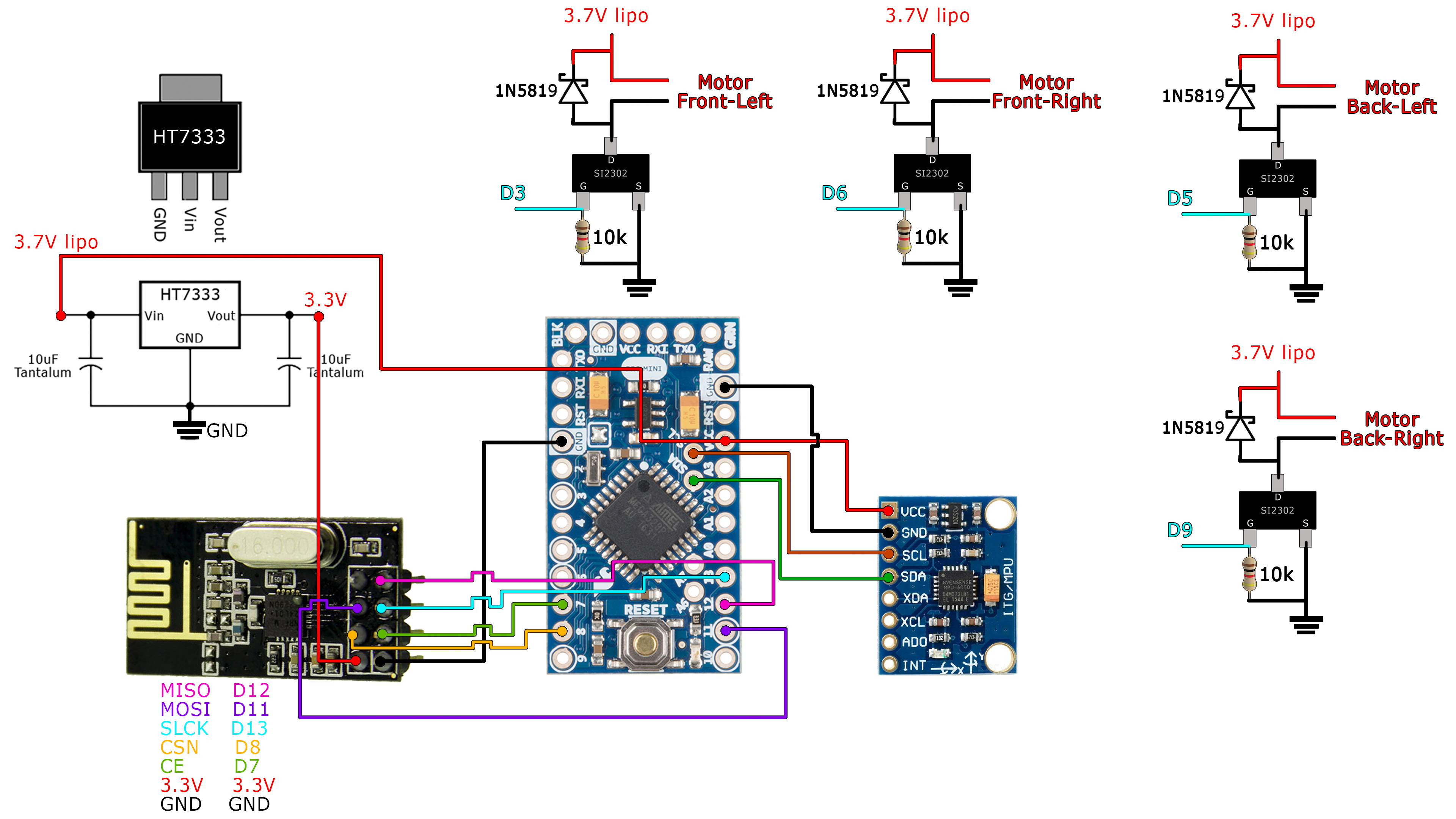
So as you can see in the schematic above, we have the Arduino pro mini which by the way, has no FTDI programmer so we will have to use an external programmer to uplaod codes to it. Any way, we have 4 MOSFETs each with its diode for backward voltage, also the MPU6050 and NRF24 modules connected. As you can see, we also have a 3.3V voltage regulator for the NRF24 radio module which works at that voltage.
More about schematic here
The voltage regulator
Well, the NRF24 module needs a very stable and also quite powerfull 3.3 voltage. I say powerfull since the moudle will draw more than 200mA of current so we need a voltage regulator that could deliver that amount. I first wanted to use the ams1117 voltage regulator but it had one problem. The voltage dropout is around 1.1V. So, if I use a 3.7V batter and substract the voltage dropout of the ams1117, I would have only around 2.6V and not 3.3V which is the amount I want.
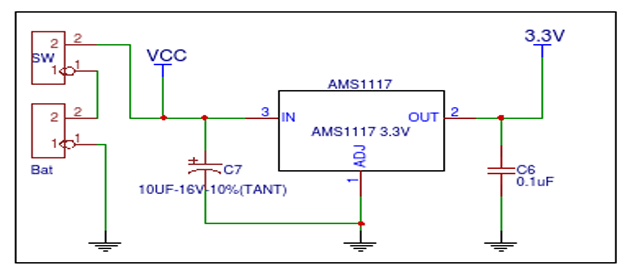
So, I don't want to use a higher voltage batter, as 7.4V, since that would complicate the project even more. That's why, I've selected another voltage regulator. The HT7333 3.3V voltage regulator with a dropout voltage of only 0.09V or 90mV.
Also, as you can see, we have to add some capacitors to smooth the voltage at the output of the 3.3 voltage regulator.
MOSFET control
Ok, so as you can see below, we have 4 MOSFETs, in this case the SI2302, one for each motor. In a brushless drone we use ESCs to control the speed. In this case we will apply a PWM signal to each MOSFET in order to control its speed. The bigger is the width of the pulse, the higher is the speed.
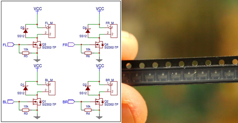
We will also need a diode between the DRAIN of each MOSFET and the battery positive input so when the MOSFET is not activated, the voltage spikes from the motor coil will have a path to flow through so we won't damage the MOSFET.
As a test, let's connect a potentiometer to the Arduino UNO to analog pin A0. Then we connect a pulldown of 10k at the gate of the transistor as in the schematic below. So when the pulse is LOW, the voltage applied to the gate is GND and whtn the pulse is high we have 3.7V at the gate. WIth the potentiometer, in the Arduino code we adjust the PWM width. COnnect a DC motor to the drain of the MOSFET and the source to ground. Remember to add the diode, it is very important!
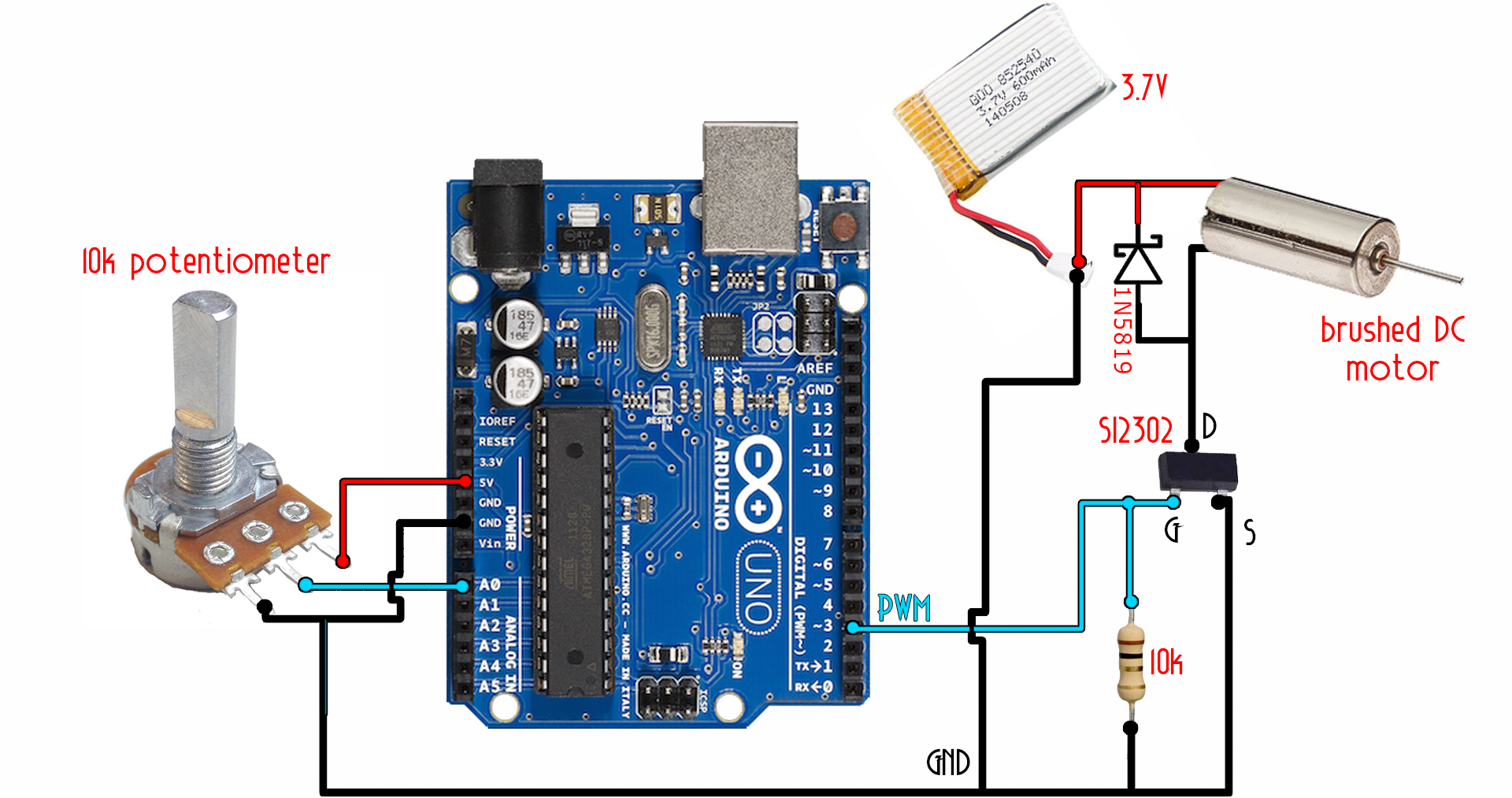
Now we should upload the next EXAMPLE code to the Arduino UNO. The code will read the value on the A0 input from the potentiometer. Then we map the value from 0 to 255 value for the PWM signal and write that pulse to digital pin D3 that is connectet to the MOSFET gate. That will control the speed of the motor. We will do the same for the drone after we have the PID control. Copy the small example code below and upload it to the Arduino.
int pot = A0; //Input from the potentiometer oin pin A0
int pwm = 3;  //PWM output on pin D3

void setup() {
  pinMode(pot,INPUT);
  pinMode(pwm,OUTPUT);
}

void loop() {
  int value = map(analogRead(pot),0,1024,0,255);
  analogWrite(pwm,value);
  delay(10);
}
Ok, so now we know how to control the speed of a normal DC motor. Once we read the GYRO data and the radio, we create the PID code and apply the PWM to each motor. So on the prototype boar we will also have 4 MOSFETs with a diode each, for each motor.
Step 3 The prototype PCB
Ok guys, so now let's mount all the parts on the PCB. We need to place the MPU6050 as centered as we can. Connect the i2c pins data to A4 and clock to A5 of the MPU6050 module. Place the 3.3V voltage regulator with the input and output capacitors, the Arduino pro mini and the 4 mosfets on each corner of the drilled PCB.
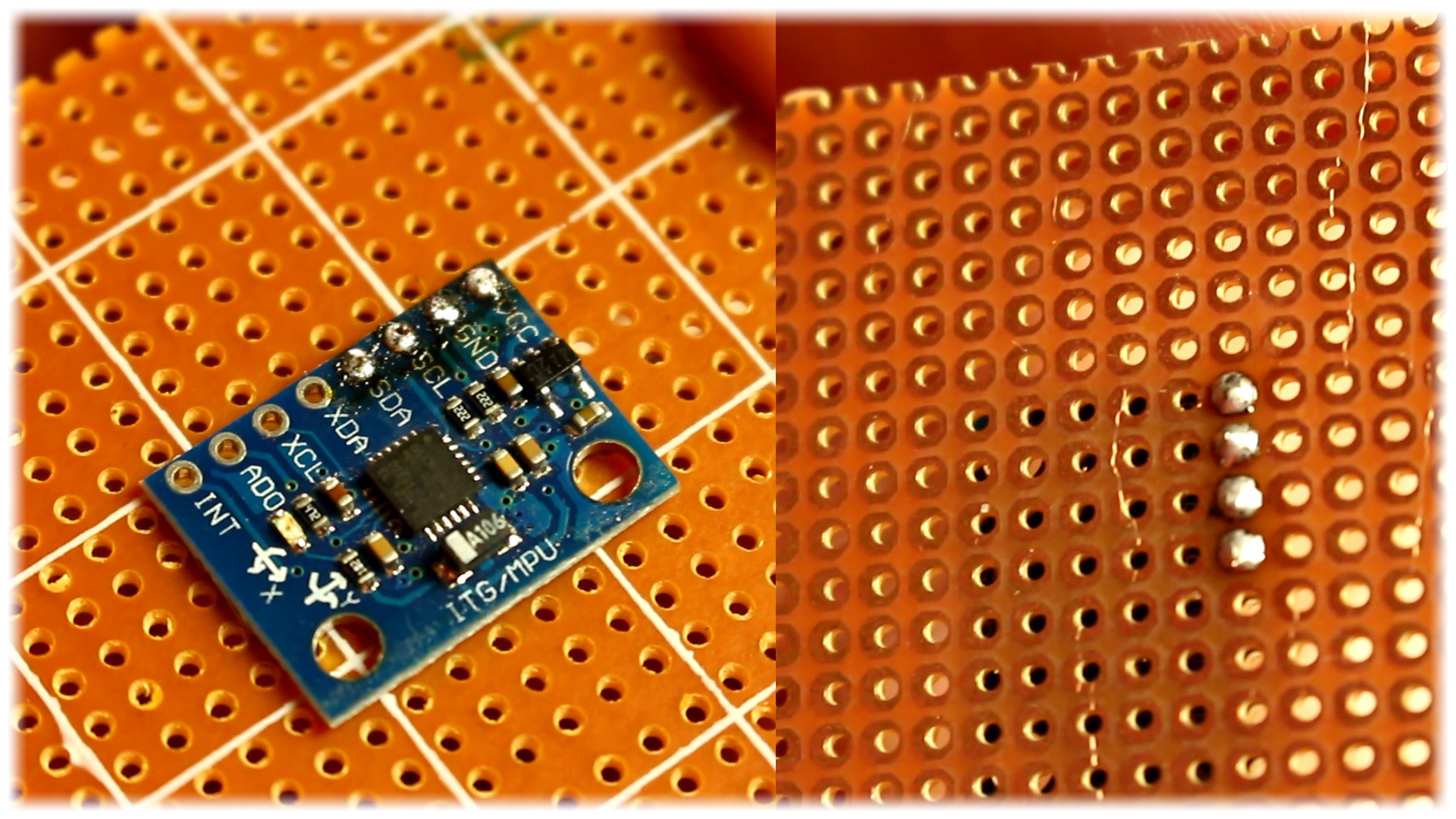
Ok, now that we have all the components, we first solder in place the Arduino and the MPU6050 module as centered we can. Next we make the SPI connections to the NRF24 radio module. Now we have all the modules connected. The next step is to solder the 3.3V voltage regulater for the NRF module with the input from the battery.
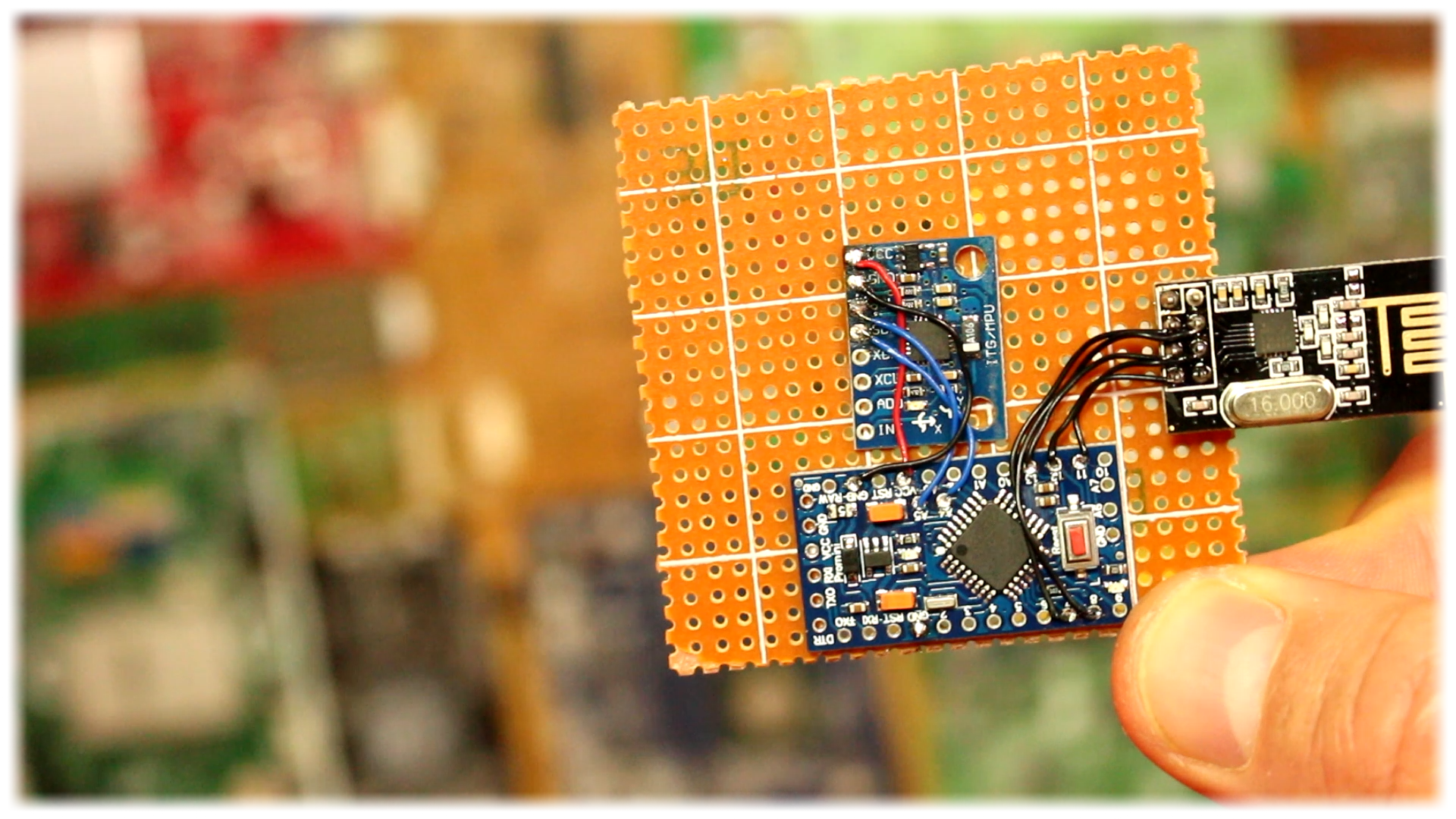
Ok, now we have the moudules and the voltage regulater soldered in place. We only have to add the MOSFETs for each motors with the gates connected to digital pins D3, D5, D6 and D9. Remember to add the 10k pulldown at the gate of each MOSFET and the diode between 3.7V and the drain of each MSOFET as well.
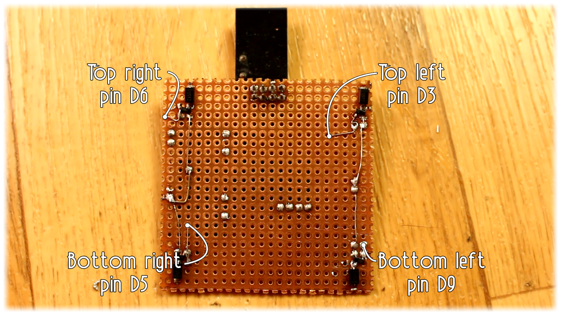
Now the board is ready. Remember to cut all the excess wire and pins in order to make the board as lighter as we can. Remove all extra part that is not necessary.
Ok, now let's mount the body and mount everything in place. The motors with the gears, the propellers and solder each motor to the MOSFETs outputs.

 About me
  History
  Let's learn
  Contact us
  Arduino tutorials
 Circuits tutorials
  Robotics tutorials
 Q&A
Q&A Blog
Blog  Arduino
  Circuits
 Robotics
  Modules
  Gadgets
  Printers
  Materials
  3D objects
  3D edit
  Donate
  Reviews
  Advertising