
 About me
  History
  Let's learn
  Contact us
  Arduino tutorials
 Circuits tutorials
  Robotics tutorials
 Q&A
Q&A Blog
Blog  Arduino
  Circuits
 Robotics
  Modules
  Gadgets
  Printers
  Materials
  3D objects
  3D edit
  Donate
  Reviews
  Advertising


Arduino Drone V2.0
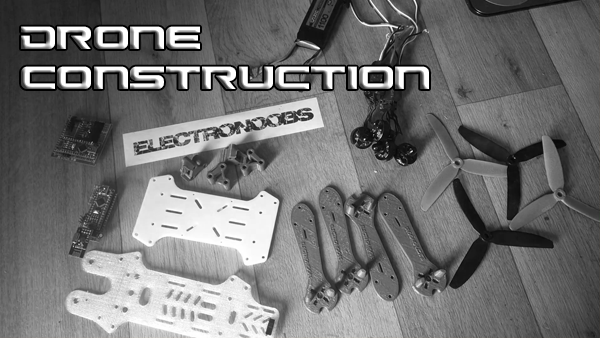 Drone construction
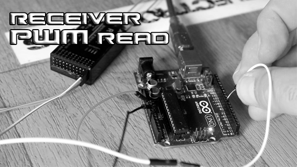 Receiver PWM read
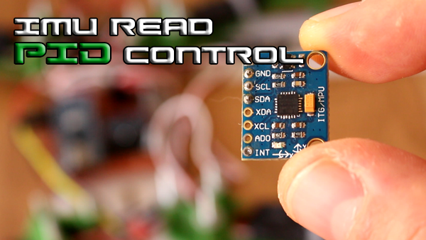 IMU + PID control
 ESCs PWM write
3.0 IMU + PID control
3.4.1 PID
Ok, so now we have both X and Y angles. Let’s start the PID process. As I talked in the PID tutorial which I recommend you to watch, PID stands for proportional, integral and derivative. In that tutorial I’ve made the PID for just one axis using a metal balance and two brushless motors. The process is now the same but using two axis and two pairs if PID constants.
Ok, so as in any PID algorithm, we need the desired value. In our case this value has to be in degrees. In the past tutorial that value was 0 degrees because I wanted the metal balance to be always horizontal. But in this case the desired value will be the received value from the radio receiver as we can see in the code below.
      	/*///////////////////////////P I D///////////////////////////////////*/
        roll_desired_angle = map(input_ROLL,1000,2000,-10,10);
        pitch_desired_angle = map(input_PITCH,1000,2000,-10,10);

        /*First calculate the error between the desired angle and
        *the real measured angle*/
        roll_error = Total_angle_y - roll_desired_angle;
        pitch_error = Total_angle_x - pitch_desired_angle;
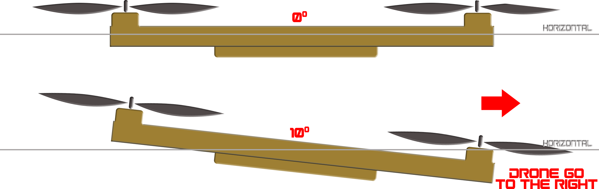
Imagine the roll axis of the drone seen from the side. And the PID desired angle is 0 so the drone flies horizontal. If we want to go to the right, all we have to do is to change the desired angle to let’s say 10 degree. That will turn the axis 10 degrees to the right and the drone will go to the right as well. So, when the roll joystick will be in the maximum position we should have a desired roll angle of 10 degrees and -10 for minimum roll value. The same applies to the pitch axis. To keep it simple, I won’t go over the YAW axis in this part of the tutorial.
Ok so now, as in the past PID tutorial we first calculate the error of the PID algorithm. This error is the difference between the real angle and the desired angle. To obtain the desired angle we first have to map the pitch and roll values from a range of 1000 to 2000 to the range of -10 to 10 degrees which is the range that we want. I do that using the map function as we have seen above.
Now that I have the error I apply the PID algorithm as in the past tutorial for both axis. The PID part are just a few lines of code as we can see below. But in this part we now have a proportional constant, an integral constant and a derivative one for each axis. Finally we restrict the range of the PID values between -400 and 400. I make sure that the throttle received value is maped to a range between 1000 and 1700. That would give us a 300us free range in which the PID values could act. If the throttle value could go up to 2000, there would be no more space for the PID to make its job because the maximum signal for the ESCs is 2000us.
/*///////////////////////////P I D///////////////////////////////////*/
    roll_desired_angle = map(input_ROLL,1000,2000,-10,10);
    pitch_desired_angle = map(input_PITCH,1000,2000,-10,10);


    roll_error = Total_angle_y - roll_desired_angle;
    pitch_error = Total_angle_x - pitch_desired_angle;

    roll_pid_p = roll_kp*roll_error;
    pitch_pid_p = pitch_kp*pitch_error;

    if(-3 < roll_error <3){roll_pid_i = roll_pid_i+(roll_ki*roll_error);}
    if(-3 < pitch_error <3){pitch_pid_i = pitch_pid_i+(pitch_ki*pitch_error);}

    roll_pid_d = roll_kd*((roll_error - roll_previous_error)/elapsedTime);

    roll_PID = roll_pid_p + roll_pid_i + roll_pid_d;
    pitch_PID = pitch_pid_p + pitch_pid_i + pitch_pid_d;

    if(roll_PID < -400){roll_PID=-400;}
    if(roll_PID > 400) {roll_PID=400; }
    if(pitch_PID < -4000){pitch_PID=-400;}
    if(pitch_PID > 400) {pitch_PID=400;}

    pwm_R_F  = 115 + input_THROTTLE - roll_PID - pitch_PID;
    pwm_R_B  = 115 + input_THROTTLE - roll_PID + pitch_PID;
    pwm_L_B  = 115 + input_THROTTLE + roll_PID + pitch_PID;
    pwm_L_F  = 115 + input_THROTTLE + roll_PID - pitch_PID;
3.4.2 ONE axis flight controller
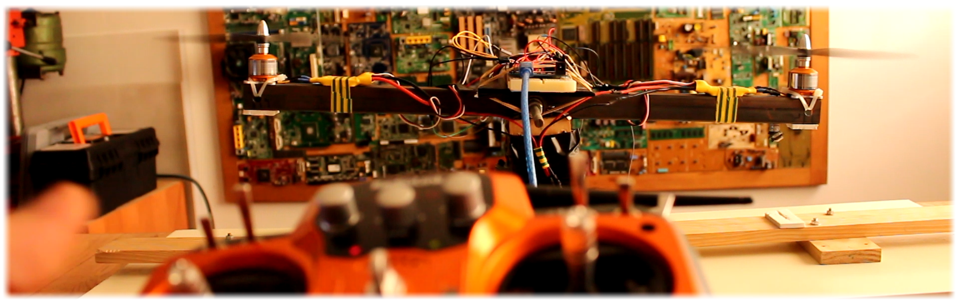
Ok so for the first test I will first use once again the one axis metal bar with the two brushless motors since I don’t have a 2 axis testing cage support. Once the final drone will be ready I will test it outside and probably have a testing cage for drones. But till then let’s see how this work. So, I receive the roll data from the receiver as we have seen in the past tutorial. I map the value that I receive to a range between -10 and 10 degrees. And this will be our desired value for the PID algorithm. We calculate the PID and then we should create the PWM signal for the ESCs.
I’ve got to say that finding this PID constants wasn’t fast. You have to do a lot of tests as in the past PID tutorial. Watch that video for more. Also the -10 to 10 degrees range wasn’t the first value that I’ve tried, so what I want to say is that depending on your drone and your entire system you’ll have to make a lot of tries and find your perfect values.
Ok so in this test the PWM signal will be attatch on pins 4 and 7. You have the one axis full test code below. The value will be the throttle signal that we receive plus the PID value and an extra 115us to make sure that the propellers will always spin at the beginning. I make the connections in the schematic below, start the radio receiver, upload the code below example to the Arduino and connect the power supply for the motors. The axis is now flying straight. When I move the roll joystick the drone will go to the left or right. The same would happen in case of the pitch axis. So, there you go. We could now control the drone and move it frontwards and backwards with the pitch channel, side to side with roll and up and down with throttle. At the same time, the PID algorithm would control the angle in case of external force. So, if I push the axis, it will get back to its initial position.
Download
I’ve got to say that this setup is not the best. First, the cables are staying in the way of the bar movement. Also, the propellers are quite big and vibrate lot. Most important, the bar is made of metal and weights a lot and at the same time is quite long so it has a lot of inertia. The motors are quite cheap and they don’t have the best response precision. What I want to say is that the PID control could improve a lot just by using better materials and a better drone frame. I hope that in case of this small 3D printed frame it will all get better.
3.4.3 TWO axis flight controller
Now as an extra I add a small part to the code that will des-activate the motors when throttle and yaw are at their lowest value for around 3 seconds and activate the motors with throttle 0 and maximum yaw value. Any time the motors are activated, digital pin 13 will turn ON and we will see the red LED shining. In order to not create big delays I use port manipulation instead of digital write. I also add a start value for the motors of 115us so the drone won’t start with 0 speed. This will reduce turbulence when lifting from ground and ensure that all the propellers will accelerate at the same time.
We’ve seen the one axis balance example. Now I create the PID for two axis. The algorithm is the same. The only thing that is different is that the desired angle for one axis will be the roll input from the receiver and pitch input for the other axis.
If the drone leans to the right, the roll angle will increase and the PID sum as well. If we want to stabilize the drone and go back to initial position, it is obvious we have to increase the speed of the right motors and reduce it to the left motors so the drone will get horizontal again. That’s why the same time, to the left front and back motors we have to add the roll PID value. And to the right front and back motors we have to subtract the roll PID value. To both front motors we have to add the pitch PID value and to both back motors we have to subtract the pitch PID value. That’s it.
Download
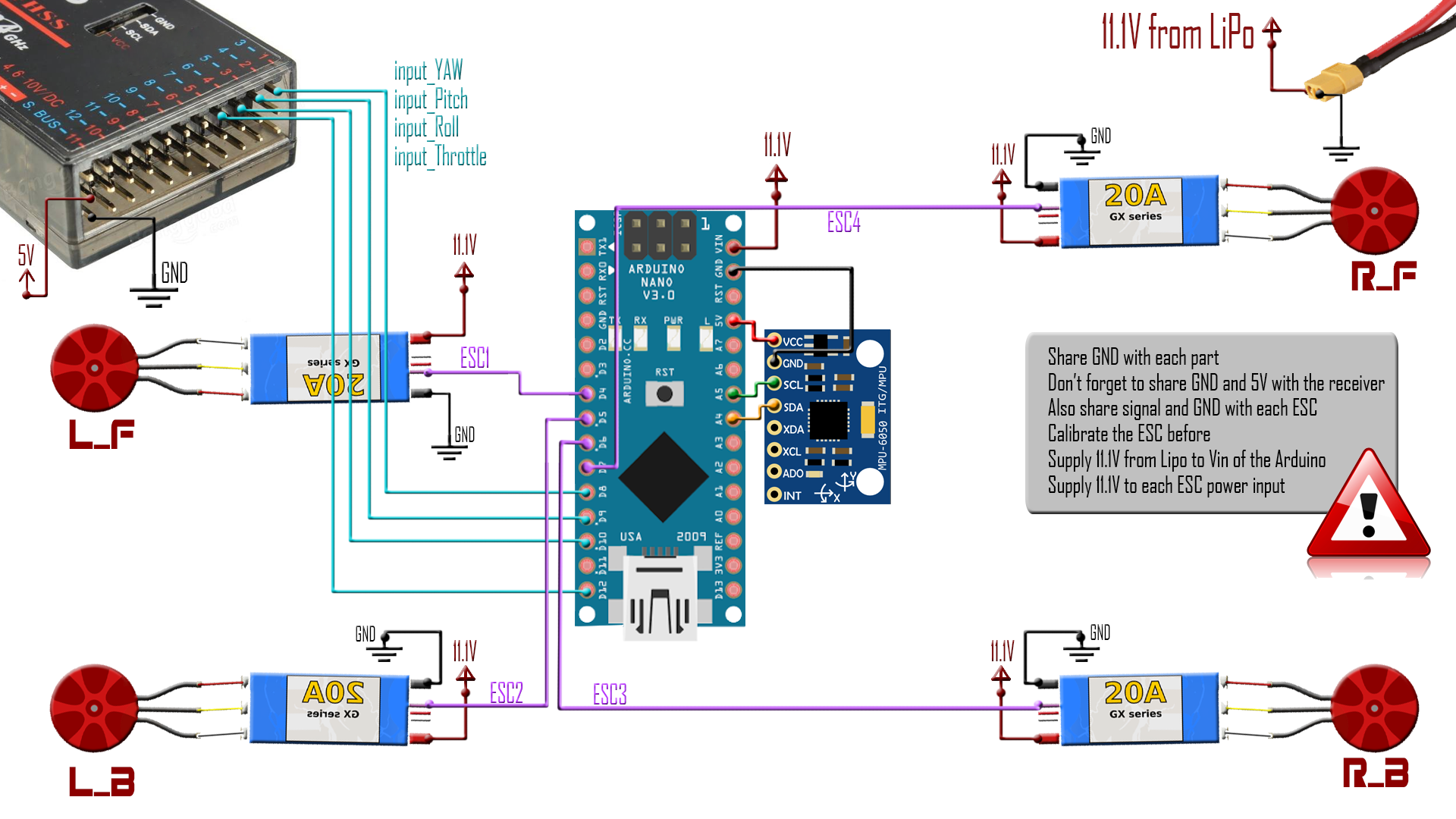
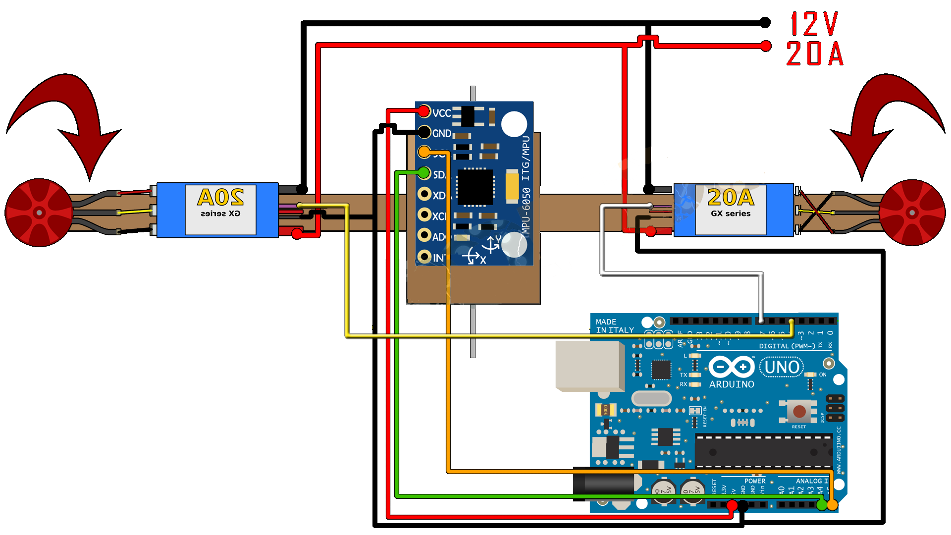
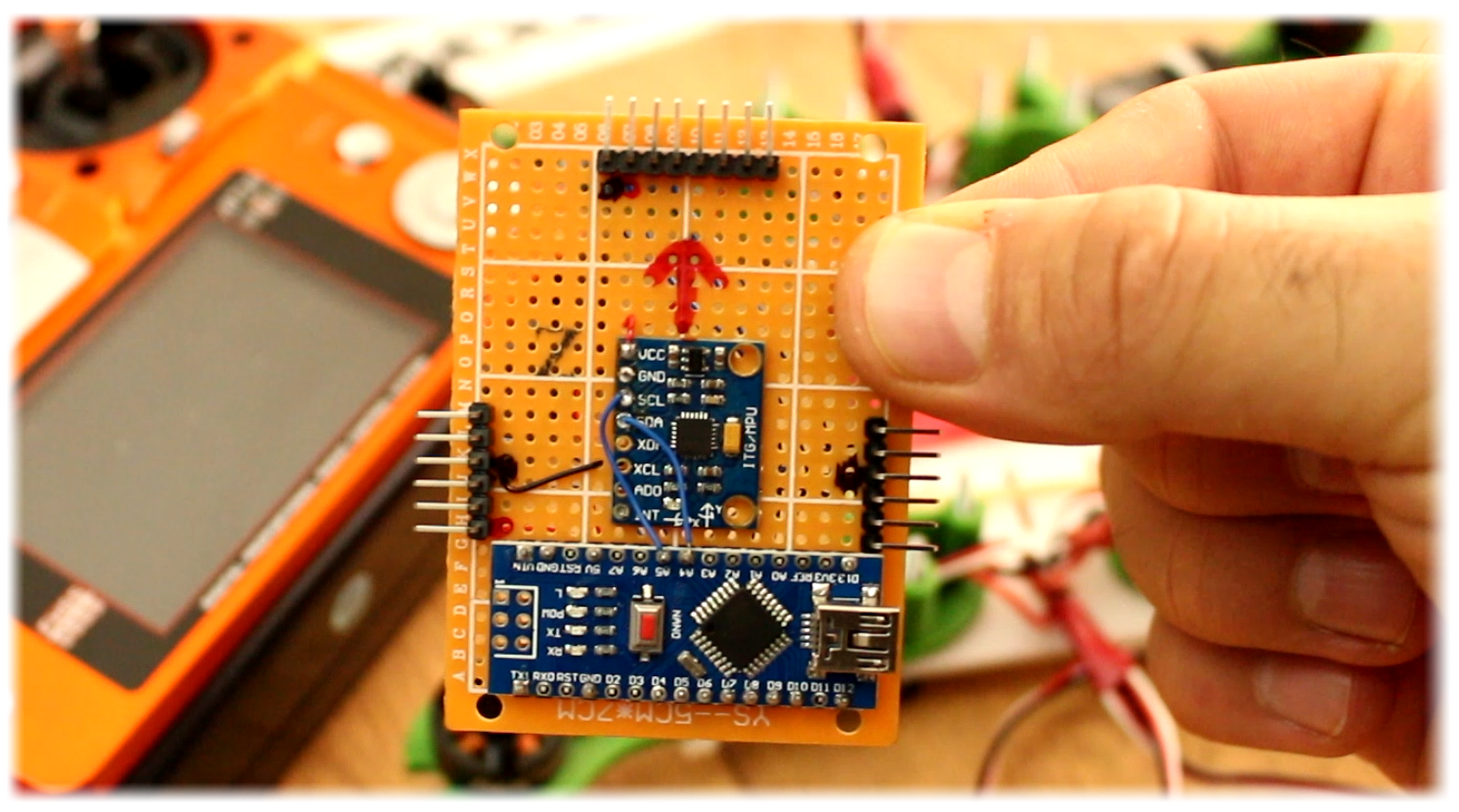
I prepare my PCB with the Arduino NANO following the schematic above. I solder the IMU directly to the PCB without pins in order to save some weight and also to have it perfectly flat. I add the male pins for the 4 channels inputs on the top of the PCB and the 4 ESCs output, two on each side. To supply 5V to the Arduino I’ll connect one of the ESCs 5volts outputs. I connect the left front motor to pin 4, the left back motor to pin D5, the right back motor to pin 6 and the right front one to pin 7. The receiver inputs are the same as in the last part, pins 8, 9, 10 and 12 of port B. Remember to also add a GND and 5V pin to supply power to the receiver.
I’m going to be sincere with you, the truth is that I failed you. I couldn’t manage to make the drone fly straight. I couldn’t find the correct PID values. I’ve made 100 tests and still noting. The first problem is that this drone is a race drone type, is so small that all the movements are very fast compared with the huge axis of the metal bar. Then the PID constants for pitch are not the same for the roll. And the last part is that I can’t try this outside. Where I live that is very difficult so I definitely need a testing cage. So, till then I can’t make it fly straight. This is what happens if you try it inside…
Any way, if you can go outside, for the tests lay on the ground the drone and activate the motors. Now increase the throttle and the drone should take off. Even if you make it fly horizontal, this drone is very difficult to control since it only has one type of sensor. That means that you should manually make all the controls. In order to keep the altitude, it should also have a pressure sensor and maybe also a magnetometer. But it is quite good for now. You have to be a good drone pilot for this drone, it is quite pro to fly.
Ok so as a recap, we receive signal from the radio receiver. We map the values from a range of 1000 to 2000 to -10 to 10 degrees for pitch and roll. At the same time, we read the IMU data and calculate the PID value depending on the desired angle received with the controller. Next, we calculate the PWM signal and apply that signal to the drone using the write Microseconds function.
At the beginning in the code we calculate the IMU error and also write 1000us value to the ESC in order to make sure that it won’t enter in the config mode. You see, almost any ESC will enter into configuration mode if you apply a 2000us pulse before you connect the battery. By the way you should make sure you have all the ESCs configured to the same range. Check my tutorial on that.
In future parts we will see how to adapt the motors speed depending on the battery voltage drop, also how to use interruptions to create the PWM signal for the ESCs and improve the entire code.
In the next part, we will see a better way to write the PWM signal to the ESCs