
 About me
  History
  Let's learn
  Contact us
  Arduino tutorials
 Circuits tutorials
  Robotics tutorials
 Q&A
Q&A Blog
Blog  Arduino
  Circuits
 Robotics
  Modules
  Gadgets
  Printers
  Materials
  3D objects
  3D edit
  Donate
  Reviews
  Advertising


Arduino Drone V2.0
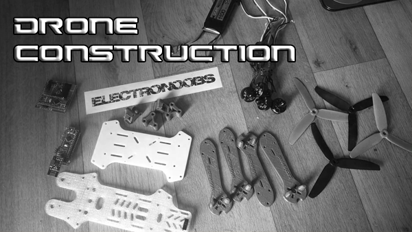 Drone construction
 Receiver PWM read
 IMU + PID control
 ESCs PWM write
2.0 Receiver PWM read
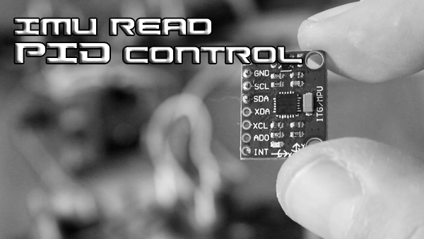
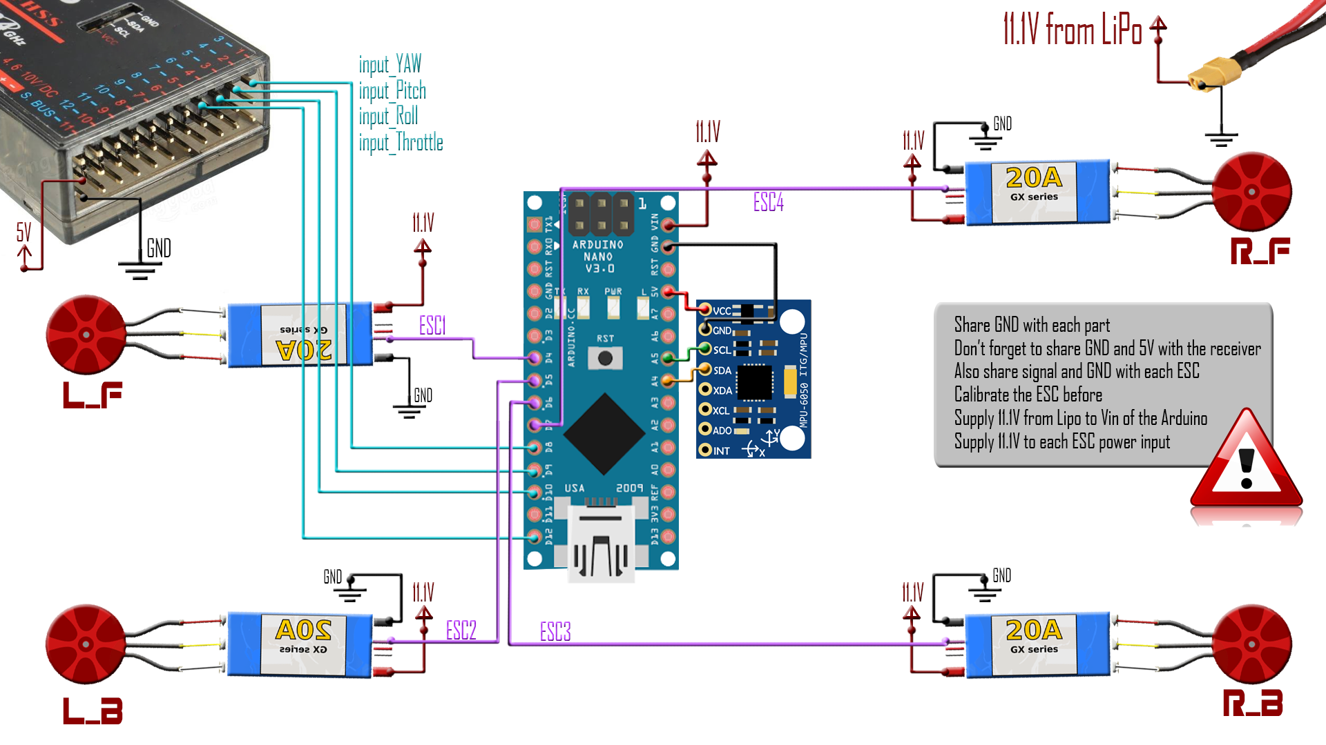
Ok so let’s begin. We could jump over the drone build part since we already done that in the past videos/tutorials. I will only center on the flight controller part of the drone. First of all, the full schematic of this tutorial is below. Motors connected to the ESCs and the ESCs to the signal pins 4, 5, 6 and 7 from port D of the Arduino NANO. We will have to create a PWM signal to these pins in order to control the motors. The IMU module connected to the i2c pins of the microcontroller, A4 and A5. And the 4 channel input from the receiver to pins 8, 9, 10 and 12 of port B .
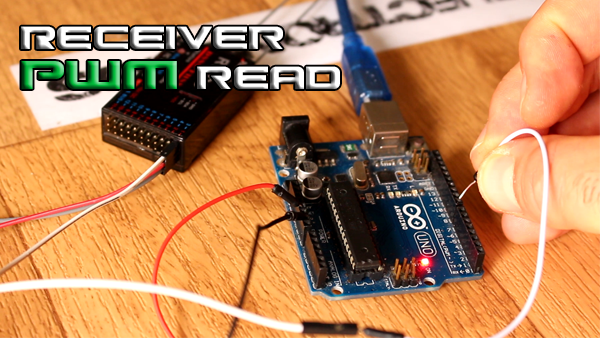
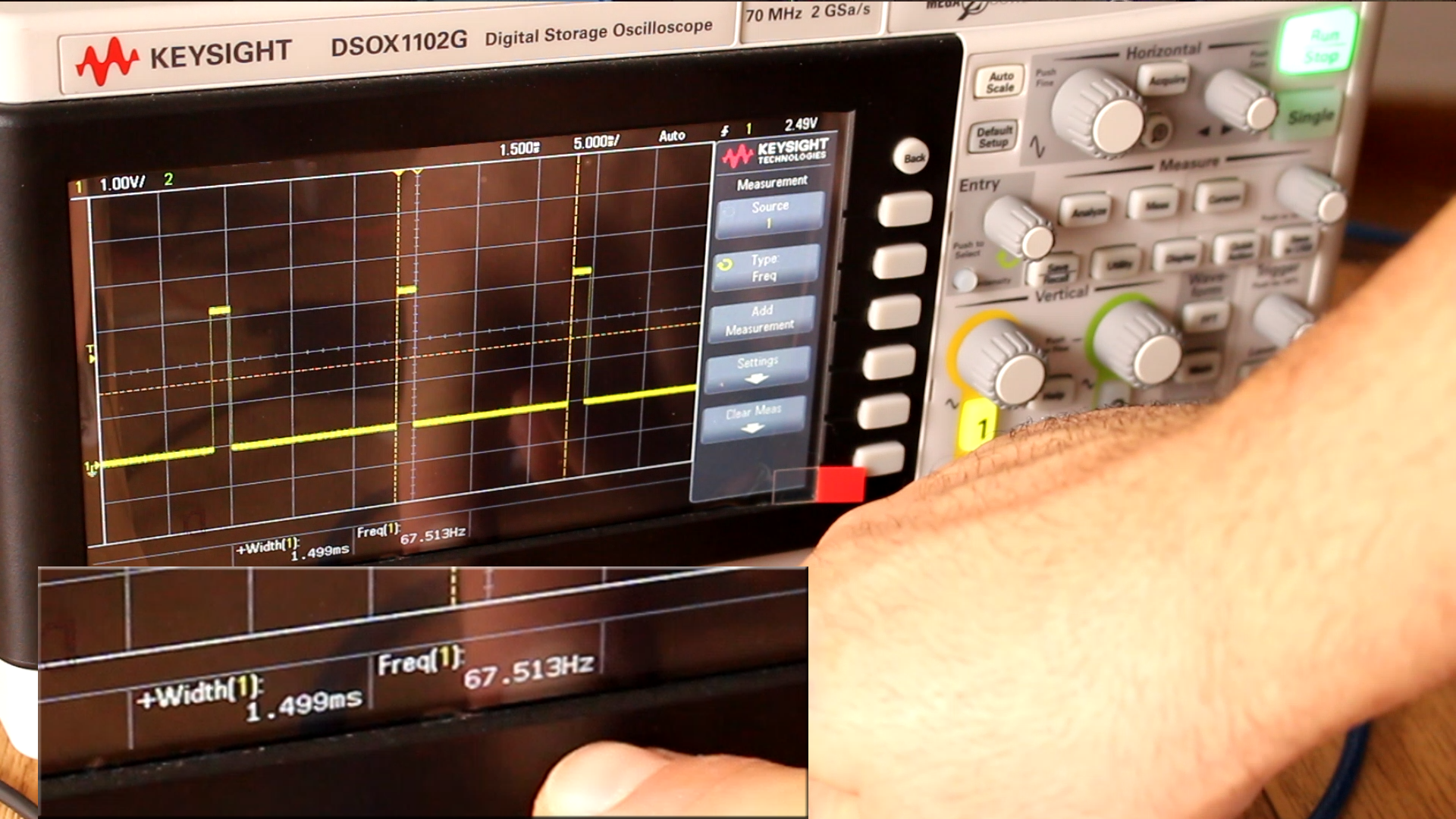
In this part we will work with this last 4 pins. First of all, let’s take a look on how the PWM signal that the receiver gives us looks. I’ve powered the receiver applying 5V to it, turn on the transmitter and connected one signal to the oscilloscope as we can see below. I’ve got a pulse width modulated signal. The pulse width of radio controllers usually go from 1000 to 2000us as we can see here. The frequency is usually in a range from 40 up to 200 hertz. In this case we have 67Hz which is a commune value. So, we have to connect this signal to the Arduino and read the 1000 to 2000 value. So how we do that?
Well first of all let’s share ground and 5V with the receiver and connect channel 1 to pin 8 of the Arduino UNO for the test. The code will work the same in case of the Arduino NANO. We could use the pulse in function to measure the pulse width. But that is not the best solution because in the flight controller code the main issue is timing. At the same time that we read the receiver PWM values, we have to read the IMU data and calculate the PID values and also write a signal for each of the 4 ESCs. Those are a lot of processes,
so, in order to not interfere and create timing issues, we should use interruptions, in this case pin state interruptions. This would interrupt the main loop each time the selected pin will change its state from low to high, high to low or both.
Ok so we activate state change interrupt for pin 8 adding this lines to the code. Pins 8 to 13 of the Arduino that uses the Atmega 328 chip, which are NANO, UNO and pro mini correspond to port register B. Now each time the signal at this input change we will go to the interrupt service routine or ISR.

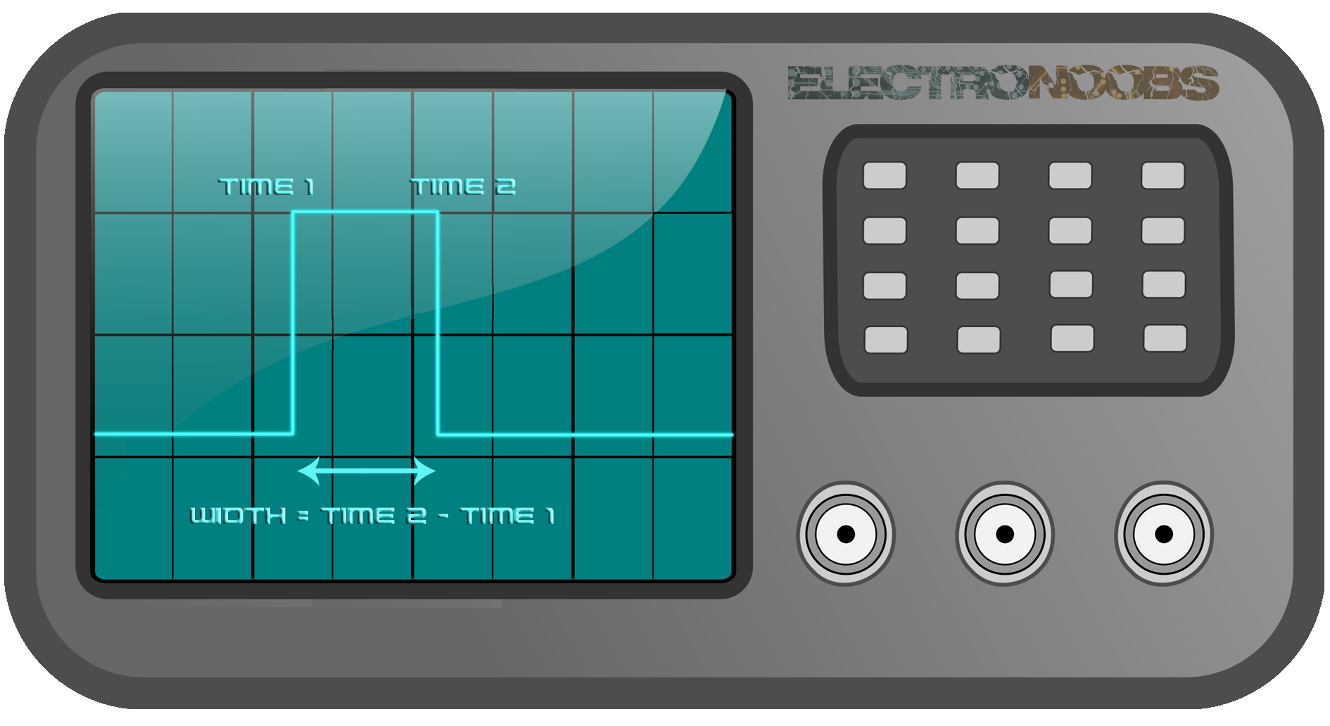
In the ISR we take a first measurement of the elapsed time and when the second change will occur we count the time once again and substract the first value in order to obtain the pulse width. Imagine this. The first value of the pin is LOW. On the rising edge we enter the interruption and obtain the time value. After a while, on the falling edge we enter the interruption again and obtain the second time value. The difference between these two time values is the actually time width of the pulse. So that easy we obtained the input value.
2.1 1 channel example
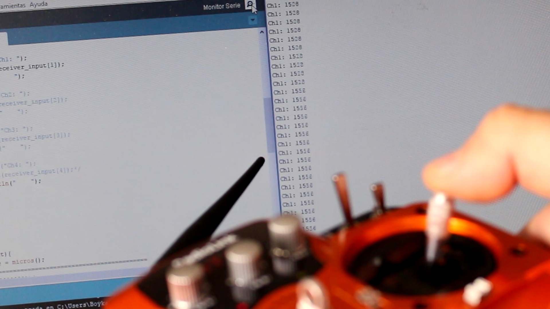
I start a serial communication and print the value on the monitor. Upload the next example to the Arduino, connect the receiver to digital pin 8 and open the monitor. As you can see when I move the joystick of channel 1 the value changes in a range from 1000 to 2000.
Download 1 channel example here:
2.1 4 channel example
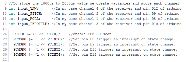
Ok so now we should do the same for the 4 channels. I will name this channels input YAW, input Pitch, input roll and input throttle. Ok but now each of this pins could create an interrupt. So for that we should first check on which pin the change occur. Using the pin port registers we check if each of the pin is high or low and at the same time if the last state was high or low. Knowing both the last and present state of the input, we could detect state change on each pin and only take the time measurement when that change occurs.
Download 4 channel example here:
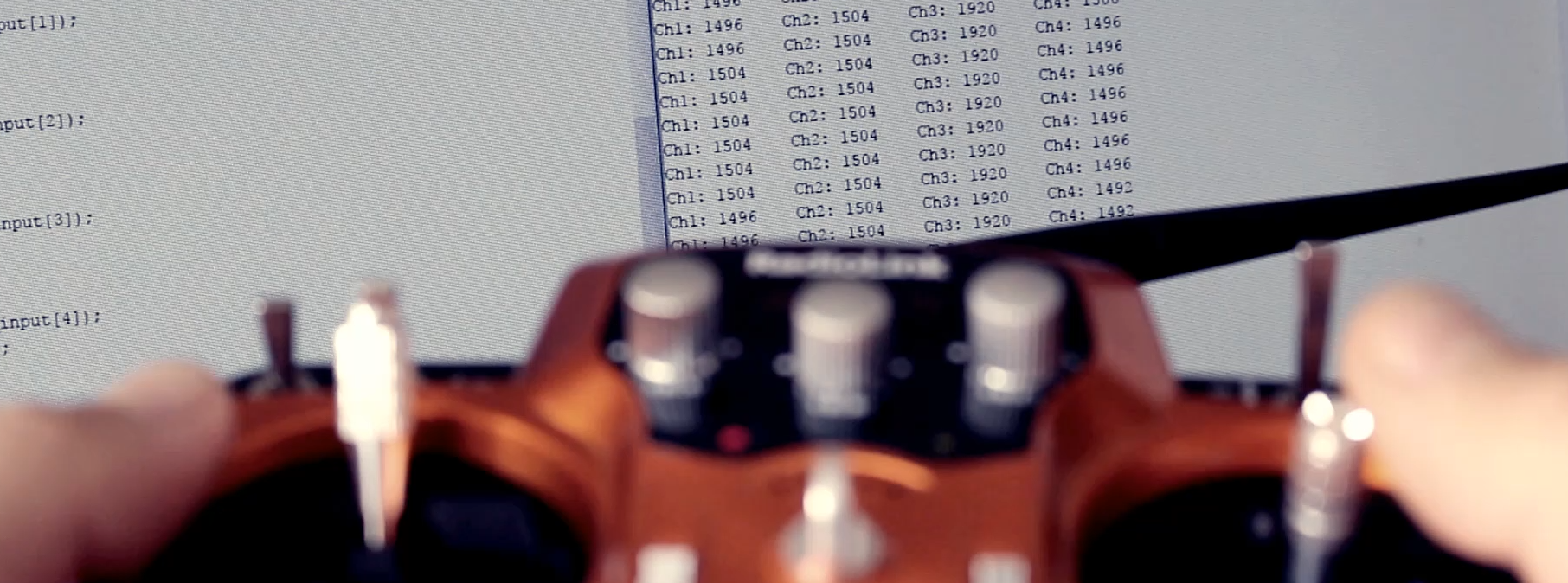
So there you go, we have the time width of each channel measured. If your radio controller dose not send a 1000 to 2000 pulse and you are not able to configure it, then you should map this values to a range between 1000 and 2000 or 0 to 1000 using the map function. We need this exact range because in future parts of the tutorial we will have to write a PWM signal to the ESCs of the motors with the same range in order to spin the motors. Where 1000 is no movement and 2000 is full throttle.
Ok so as a recap of this first part, we first define our variables for each channel, for the time count and a few more variables that we will use. Next, define the configuration of the input pins in the setup loop in order to activate the interruption triggering. The interruption routine is defined separated of the main loop with a vector corresponding to the interruptions created by the pins that we have selected and in the main loop the only thing that we do in this example is print the values on to the serial monitor. We will have to delete these lines on the final code and add all the remaining parts.
Well In the next part we will read the data of the IMU and create the PID control for 4 motors using both gyro and accelerations data.
Ok, now that we have the receiver signal let's read the IMU data.