Today we have an awesome project and also a bit dangerous. We are making a homemade full sine inverter of around 500W and check the video till the end if you want to see the results. I’ve made some tests based around the EGS002 driver board and other smaller modules. But this driver could read feedback and control some IGBTs in order to create a steady high voltage sine wave just as our home outlets. As you can see the PCB is quite big and that’s because it has a few different parts and is also made for a lot of power. We will go over each part so you will understand how such an inverter works. I wanted to see if it could be cheaper to make a homemade inverter and also learn something new. So guys, let’s get started and be careful working around high voltage.
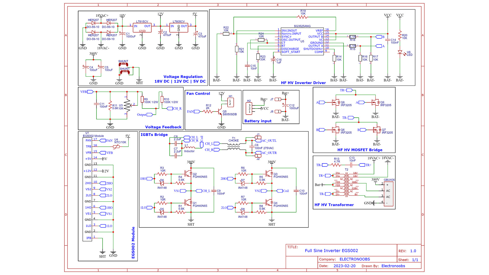
This is the scheamtic for this awesome project. It has a lot of parts but is not that complicated. We have the main input called Battery input. Here we should connect 12V from a battery with enough current (>10A) output. This input is connected to a switch so we could turn on/off the supply for the rest of the circuit. 12V are connected then to the HF HV part for high frequency high voltage generator. This part is using the SG3525 driver and a transformer to generate 380VAC, 220VAC and 18VAC using 4 MOSFETs in a bridge. Then we have the voltage regulation block. Here we use diode rectifiers to get DC from AC. So we will have 380VDC and 18VDC. Then we use two votlage regulators to get stable 15VDC adn 5VDC. We add two huge high voltage capacitors to store the 380VDC and use it later with the final block, the IGBT Bridge. The driver will apply SPWM signals to this IGBT bridge and create sine shape signal of high voltage. That's how the inverter works. A small extra block is the feedback. The driver will read the feedback adn adjust the output value according to that. We can use the potentiometer to increase or decrease the output voltage.
We have the EGS002 board in the middle and that is connected to the rest of the circuit. This board only costs a few dollars and it seems that it works quite well. The main input will be on the bettery pads, and here we would connect a 12V battery for example of decent current (the board is for 500W). The board has these parts: Battery input, high voltage generation, voltage regulation, driver, IGBT bridge and AC output.
For the first step, to generate higher voltage, I’m using a special driver together with a transformer and 4 MOSFETs. This driver is the SG3525 and it will create a high frequency square wave applied to the MSOFETs bridge. That will apply power to the transformer and that’s how we get 380V AC. To pass it to DC voltage, we add a full bridge rectifier and two big high voltage capacitors to store the charge. So that’s how we get 380VDC and that’s the first step. The transformer I’m using has 3 different outputs. As you can see on the PCB, it has 18VAC, 380VAC and 220VAC. So we also get the 18VAC and pass it through some diodes and capacitors to get 18VDC. Then we add the regulators for 15V and 5V. We need those voltages for the driver, it requires both 15V and 5V. It uses 15V to control a cooling fan. I also add a small BJT transistor connected to a connector for that fan. You see, the driver also has a thermistor input to detect the temperature. If the IGBTs are getting too hot, it will start the fan and cool them down. All we need to talk about is this last part and that will create the high voltage sinusoidal wave. We have 4 IGBTs and they receive an SPWM signal from the driver board. They control the 380V DC and create a high voltage AC signal together with a huge coil at the output and high voltage ceramic capacitor. At the output, we also add a choke filter and we would have our inverter output on those two pads for L and N. To measure the current, we also add two shunt resistors between the 380VDC ground and the IGBT ground, so the driver could measure the current and limit it.
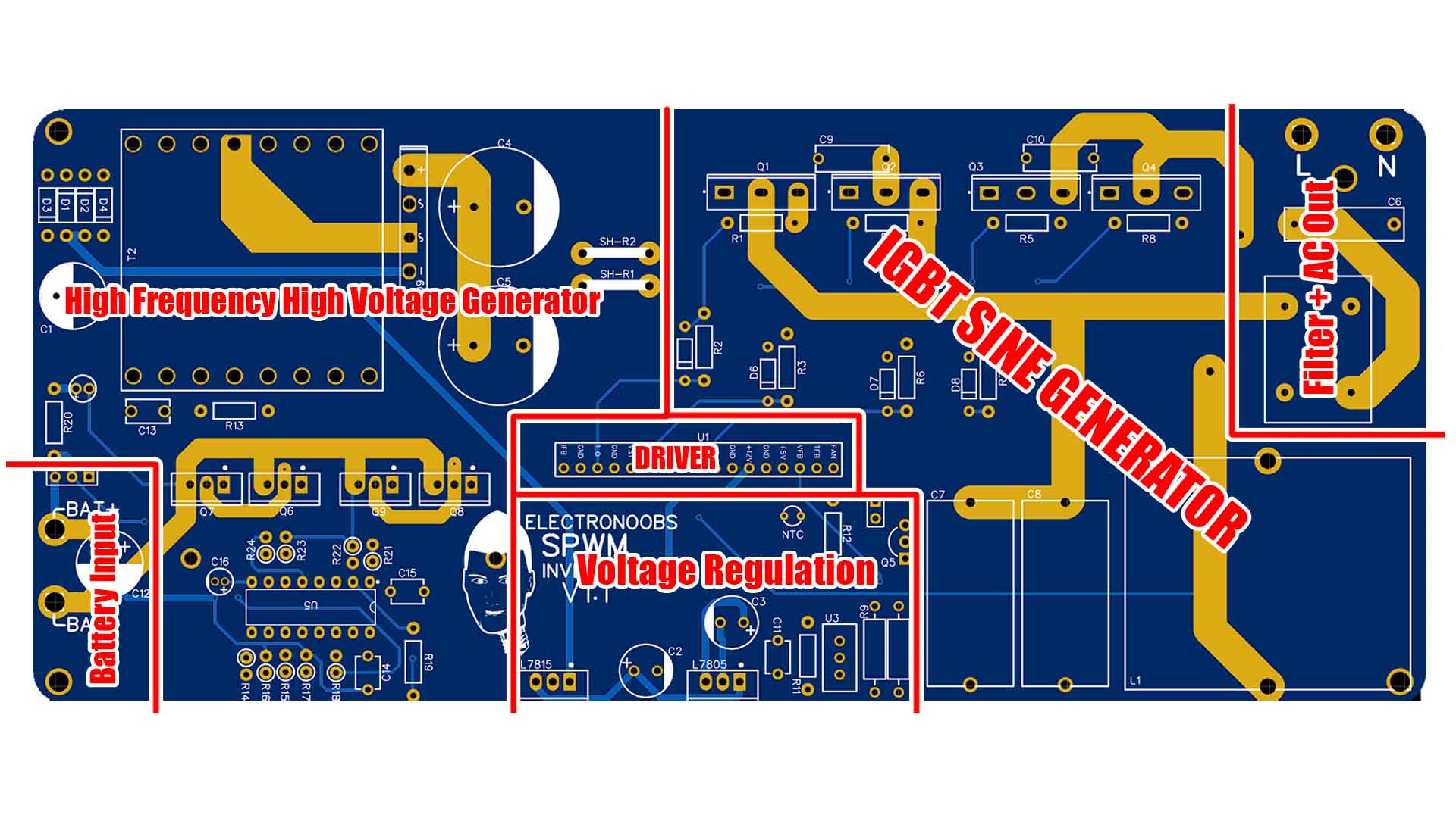
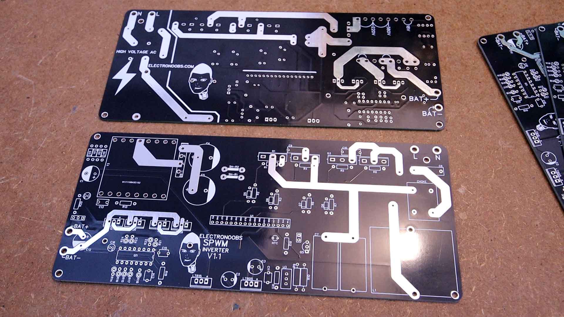
This is the PCB I’ve made for this project. It is quite big but don’t worry, the circuit is not that complicated. The size is of 210mm by 90mm but depending on your designing skills and the time you invert for such a project, you could make it even more compact. So you can download the GERBERs from below and go to PCBWAY and order your own board. Click the quote now button. Select the size, amount of PCBs and the color, in my case I want it to be black. Save to cart and click the upload GERBERs button. Upload the GERBER and make the order. In a few days you receive the PCBs and they look awesome. I think the black solder mask is my favorite. As you can see, the PCB has exposed copper tracks. That’s because I want those tracks to withstand more current so later we could add solder on top so they would get thicker.
The part list is a bit long but not complicated at all. We need the driver, the IGBTs, some coils, regualtors and capacitors. For the high voltage generator, I've just bought a module for 10€ and took the driver, transformer and small components out of it. In this way I save some money and also make sure the transformer is the one that I want. Check the schematic in order to know the resistor values.
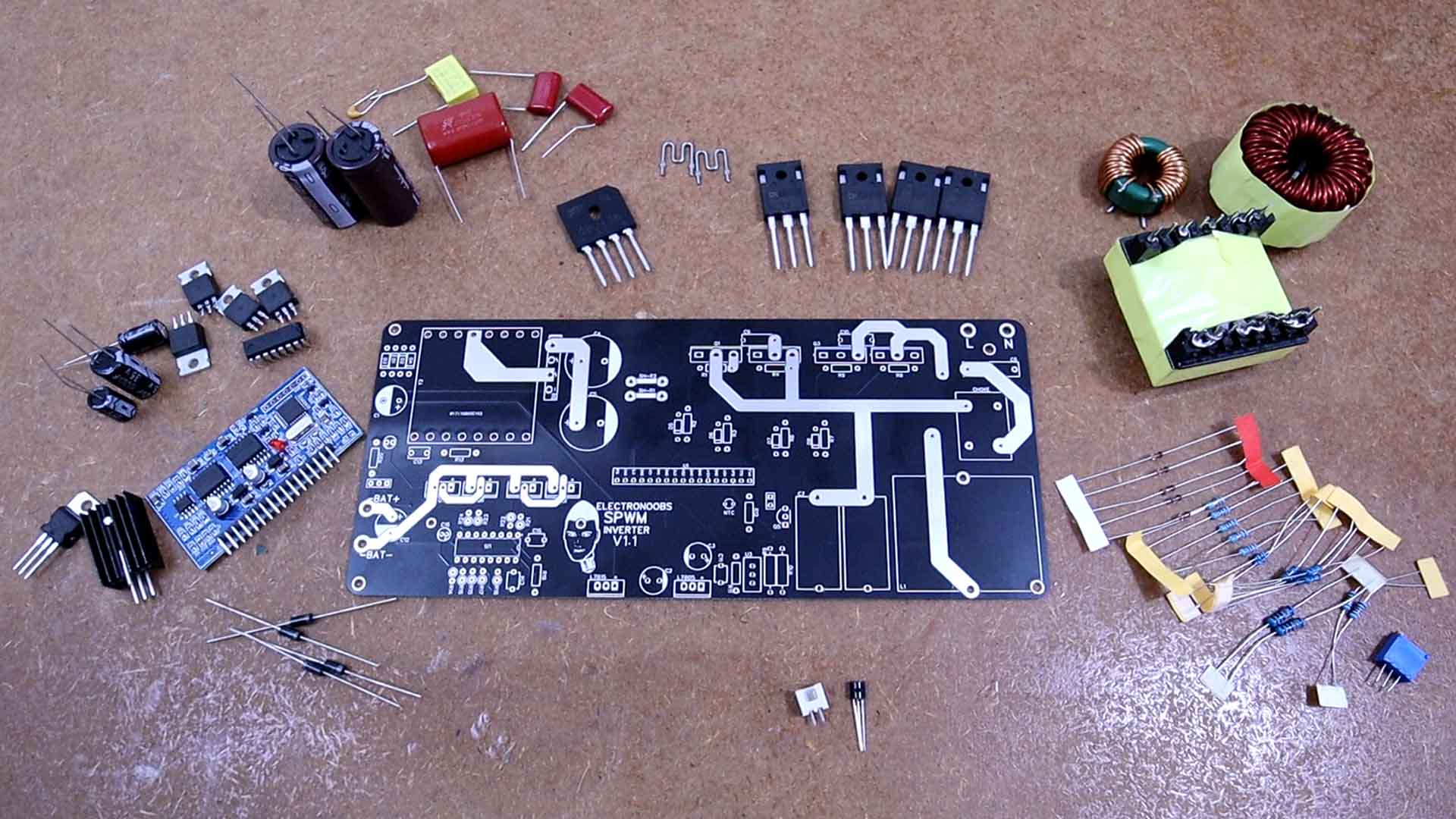
Is time to assemble it and the list above is pretty much all that we need. Capacitors, IGBTs, transformers and coils, resistors, diodes and potentiometers. The drivers, regulators and so on. Pretty basic components.
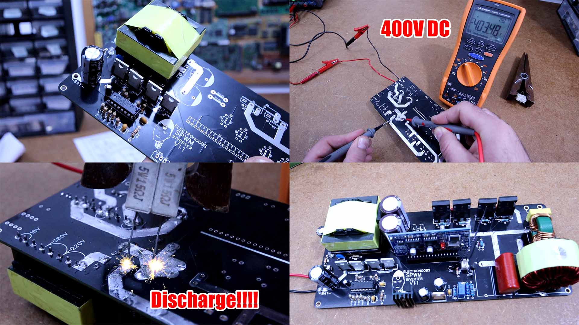
Step 1: HF HV Generator. We start with the high frequency and high voltage generation. This part of the circuit is based on this board that I’ve bought from AliExpress. Basically, to spare some money, I’ve got the components out of this cheap module (IRF3205 MOSFETs, transformer, resistors and capacitors). So all I have to do is to follow the schematic and solder the driver, some resistors, the transformer, the full bridge rectifier and the high voltage capacitors. Now I have those in place so we could test the output. Be careful, this high voltage could hurt you, especially, make sure that you discharge the capacitors, they could store a huge high voltage charge. I connect 12V at the input and measure the voltage at the capacitors. If it is around 380 -390V, we could continue. But make sure you discharge the capacitor through some sort of power resistor as I did here with some wood pliers. Be careful.
br>
Step 2: Volage regulators. Now I add the 18V diodes and capacitors and the voltage regulators. Once I have those in place, I test the values once again. We should have 18V DC, 15V and 5V. If we have those values we could continue, but remember to discharge the capacitors once again. I can’t stress this enough.
Step 3:IGBTs bridge + coil and capacitor. Now we add the final part, the AC output part with IGBTs, coils and capacitors. I start by soldering the IGBTs. Then I add two 100nF capacitors. I add the gate diodes and resistors. Then I finally ad the huge coil. I also add the high voltage capacitor. And finally I add the choke and output capacitor.
Step 4: Extras. Additionally, I also add the shunt resistors which are basically just a piece of metal with a very low resistance, something around 10 milliohms.
I also add the thermistor, the BJT for the fan and the rest of the connectors together with the feedback resistors and potentiometer.
All is left is to add the driver module. And the inverter is ready.
Now that everything is in place, here comes the scary part, testing the inverter. To be honest I’m a bit afraid of connecting this because it works with high voltage and a lot of power. But here it goes, I connect the oscilloscope at the output and also a multimeter in AC mode. Now connect 12V from my supply. The signal looks just perfect. A sinusoidal wave. Use the potentiometer to adjust the value. So connect a multimeter in AC mode at the output and rotate the potentiometer till you get 230V for Europo. (This inverter need changes for 115V for US). Now I can add a load, for example we start with a light bulb. And it turns on with no problems and the voltage is very stable and the waveform is perfect. I measure the input current and it is around 5 amps which at 12 volts represents a power input of 60 watts. Now I measure the current at the load. Is around 176mA which at 230V AC is around 40W of power output. So something around 20W are wasted on the inverter without any load and under laid we are still looking at 80 something percent efficiency which is not bad. For another test I will connect a 150W Dremel. I start it up and it works with no problems. The signal gets only a little bit affected but it seems to work just fine.
So guys, that’s how you could make a sinusoidal homemade inverter. Have in mind that the power is limited by the first high voltage generator. This board from AliExpress was advertised to output 500W. So if you want more power, you should add a few of these boards in parallel to get 380V but a lot more current. Actually, if you open a commercial 2000W inverter, you would see that it has 2 or maybe even 3 transformers and the rest of the board is the same. The IGBTs and the output coils and capacitors. Feel free to use my schematic, my PCB files and my tutorial to make the same project or even improve it. I’m quite satisfied with the results. It gives me a steady high voltage sinusoidal output of 50Hz and that’s exactly what it should do. I’m glad I was able to pull off such a complicated and dangerous project. If my videos help you, consider supporting my work on my PATREON or a donation on my PayPal. Thanks again and see you later guys.