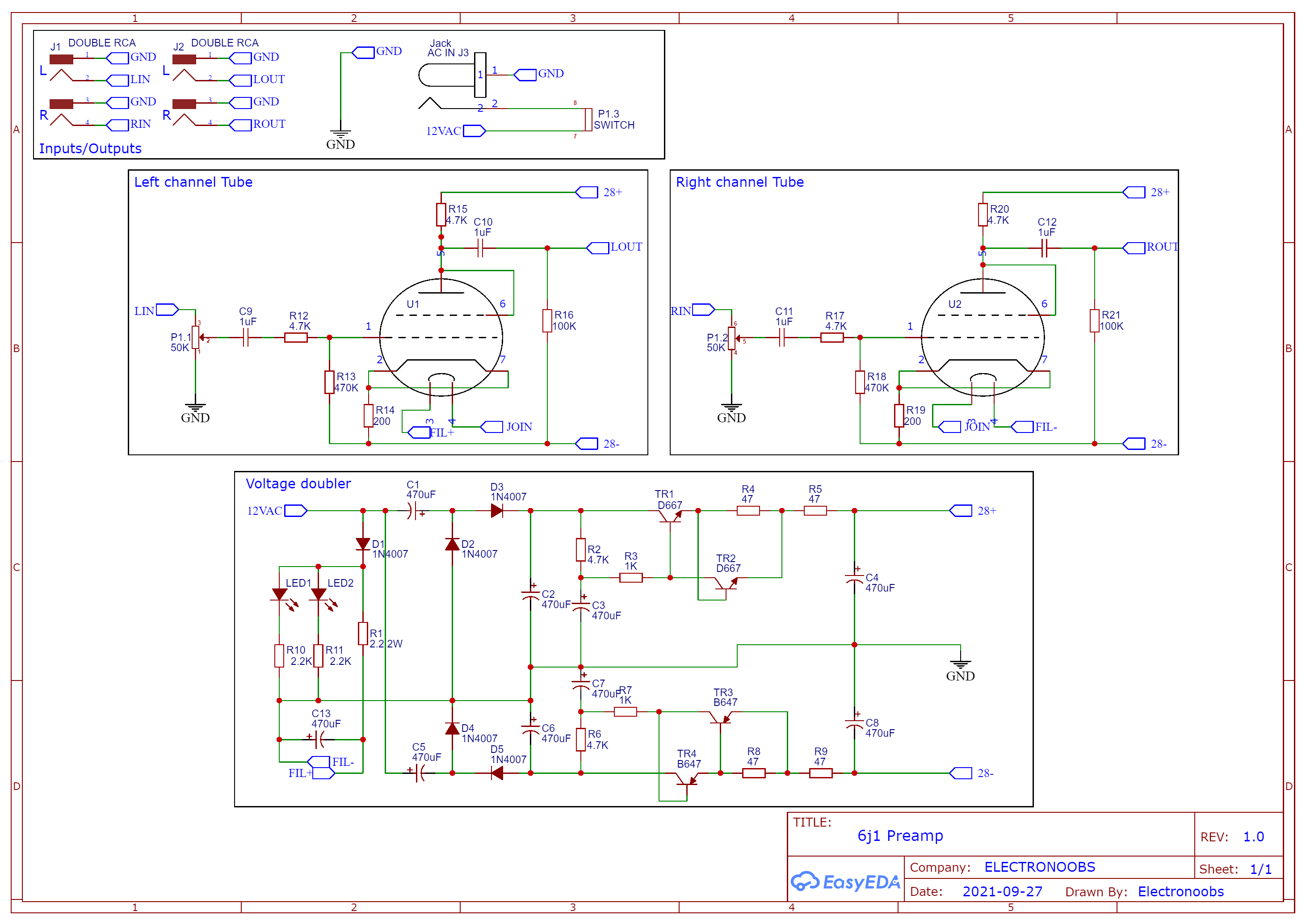
This is the schematic for the entire PCB. The bottom part is the voltage doubler that will use the 12V AC input and create 28V DC and -28V DC. We use this to supply the tubes. The 12V AC is also connected to the tube filaments which are in series and connected on pins 3 and 4 of each tube. That will heat the filaments up creating loose electrons. The potentiometer is connected between the audio input and the pin 1 of each tube. The output is on pins 5 of the tubes and connected to the RCA connectors. We ahve two LEDs each witha 2.2K resistor and those will go bleow the tubes and make them glow blue in my case, but you can use any other color for those LEDs. That's it.