This module will create the ticks that are 16 times faster tahn the baud rate, in this case 9600 bauds/s.
/*Imagine that the baud rate you want to work with is 9600. The clock of my
FPGA is 50MHz. If we want the "TICKS" to ahev 16 times the frequency of the UART signal
we need a frequency 16 times the 9600Hz.
The width of the UART signal is 1/9600 equal to 104us. The width of the main clock is 1/50Mhz equal to 20ns
How many 20ns pulses we need to cont to get to 104us/16??? Well (104000ns/16)/ 20ns = 325 pulses (
That's why in the top we set baud rate to 325)
*/
module UART_BaudRate_generator(
    Clk                   ,
    Rst_n                 ,
    Tick                  ,
    BaudRate
    );

input           Clk                 ; // Clock input
input           Rst_n               ; // Reset input
input [15:0]    BaudRate            ; // Value to divide the generator by
output          Tick                ; // Each "BaudRate" pulses we create a tick pulse
reg [15:0]      baudRateReg         ; // Register used to count


always @(posedge Clk or negedge Rst_n)
    if (!Rst_n) baudRateReg <= 16'b1;
    else if (Tick) baudRateReg <= 16'b1;
         else baudRateReg <= baudRateReg + 1'b1;
assign Tick = (baudRateReg == BaudRate);
endmodule
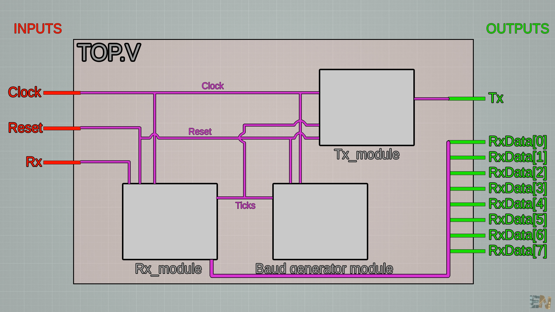
The top.v module, will merge all modules together using wires. In this way, we could send and receive at the same time using all the modules.
module TOP(
Clk ,
Rst_n ,
Rx ,
Tx ,
RxData ,
);
/////////////////////////////////////////////////////////////////////////////////////////
input Clk ; // Clock
input Rst_n ; // Reset
input Rx ; // RS232 RX line.
output Tx ; // RS232 TX line.
output [7:0] RxData ; // Received data
/////////////////////////////////////////////////////////////////////////////////////////
wire [7:0] TxData ; // Data to transmit.
wire RxDone ; // Reception completed. Data is valid.
wire TxDone ; // Trnasmission completed. Data sent.
wire tick ; // Baud rate clock
wire TxEn ;
wire RxEn ;
wire [3:0] NBits ;
wire [15:0] BaudRate ; //328; 162 etc... (Read comment in baud rate generator file)
/////////////////////////////////////////////////////////////////////////////////////////
assign RxEn = 1'b1 ;
assign TxEn = 1'b1 ;
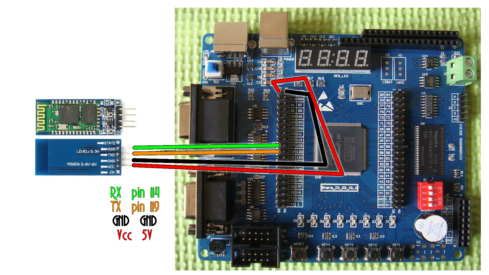
assign BaudRate = 16'd325; //baud rate set to 9600 for the HC-06 bluetooth module. Why 325? (Read comment in baud rate generator file)
assign NBits = 4'b1000 ; //We send/receive 8 bits
/////////////////////////////////////////////////////////////////////////////////////////
//Make connections between Rx module and TOP inputs and outputs and the other modules
UART_rs232_rx I_RS232RX(
.Clk(Clk) ,
.Rst_n(Rst_n) ,
.RxEn(RxEn) ,
.RxData(RxData) ,
.RxDone(RxDone) ,
.Rx(Rx) ,
.Tick(tick) ,
.NBits(NBits)
);
//Make connections between Tx module and TOP inputs and outputs and the other modules
UART_rs232_tx I_RS232TX(
.Clk(Clk) ,
.Rst_n(Rst_n) ,
.TxEn(TxEn) ,
.TxData(TxData) ,
.TxDone(TxDone) ,
.Tx(Tx) ,
.Tick(tick) ,
.NBits(NBits)
);
//Make connections between tick generator module and TOP inputs and outputs and the other modules
UART_BaudRate_generator I_BAUDGEN(
.Clk(Clk) ,
.Rst_n(Rst_n) ,
.Tick(tick) ,
.BaudRate(BaudRate)
);
endmodule
To control the LEDs and send data, I'm using an Android App. Make the connections as below, uplaod the synthesis to the FPGA and install the Android App. Make sure you enable unknown apps to be installed to your smartphone. First, bind with the HC06 bluetooth module. Use 0000 or 1234 password. Open the App, click the bluetooth symbol, select the HC06 module and connect. Now send numbers and see the LEDs change.