
 About me
  History
  Let's learn
  Contact us
  Arduino tutorials
 Circuits tutorials
  Robotics tutorials
 Q&A
Q&A Blog
Blog  Arduino
  Circuits
 Robotics
  Modules
  Gadgets
  Printers
  Materials
  3D objects
  3D edit
  Donate
  Reviews
  Advertising


DC non invasive current clamp for oscilloscope DIY
0.0 Basic intro
Having an oscilloscope it's a very nice thing. It's a quite useful tool. But with the basic probes you could only observe voltage values. What if we want to observe current???
There are many types of oscilloscope probes each with its own field of application. The probe takes care of the very critical coupling between the measured object and the oscilloscope. In this video we will talk about current probes, and to be more specific about the non-invasive current probes which means that we don’t have to directly connect it to the open circuit in order to take a measurement.
Currents can be measured by measuring the voltage across a known resistance. A major disadvantage is that the circuit has to be opened to insert this shunt resistor. We’ve seen this kind of current meter in one of my past tutorials of the Arduino based multimeter. You have the link of that tutorial below.
In this video we will do something different because that additional resistance can also affect the measurement by its burden voltage. Currents can also be measured with a current probe, also known as a current clamp. These probes don't have the disadvantages of shunt resistors as we’ve just described. A current probe is simply clamped over the current carrying wire and the circuit doesn't have to be opened which is a huge advantage.
Current probes are roughly divided into two types: AC and DC current clamps. I’ll try to explain how both of these types work. To understand that let’s first have a look at my hantek current clamp that I’ve just receive. It’s a quite useful tool.
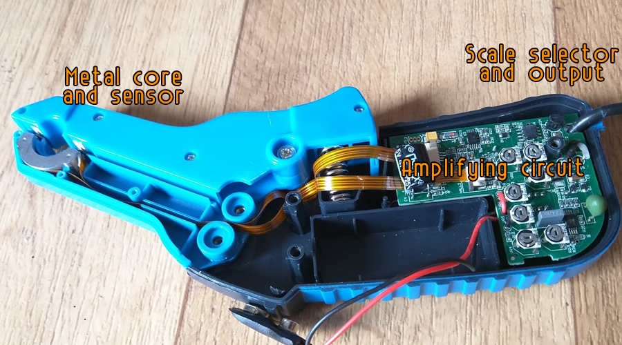
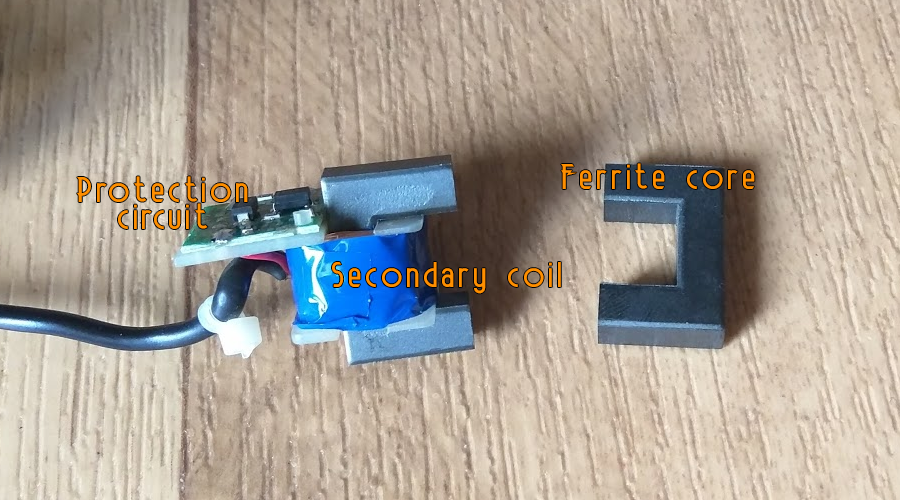
Than how dose it work? For that I will first open the case and observe its components. As I guessed, the circuit is quite simple. On the tip we’ve got our metal magnetic core that will carry the magnetic flux thru it. Here we should also have some kind of sensor and that’s it. Next, we have the main circuit where we will probably find an amplifier and the scale selector circuit since we have two different scales to choose. Here is the output that goes to the oscilloscope. So, knowing these components let me now explain a little bit how this all work.
Buy the hanteck clamp here:
1.0 AC current clamp
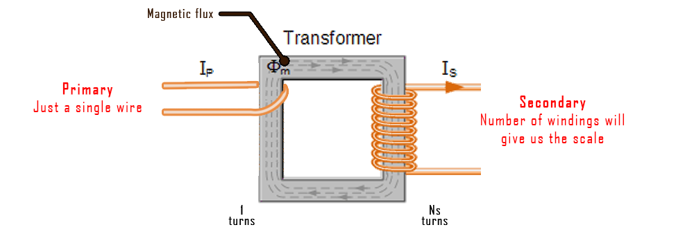
As I said current probes are divided into two types: AC and DC current clamps. The AC current clamp is basically a transformer. The primary winding is the conductor who carries the to be measured current, in this case a simple wire and the second winding is fixed onto the core and is connected to the oscilloscope. This is a passive probe and can handle only alternating currents. A normal transformer can't deal with DC currents. Therefore, the operating principle of DC current probes is rather different from AC probes. Let’s first see how to build our own AC current probe. All we need is a transformer core and some copper wire to create our windings.
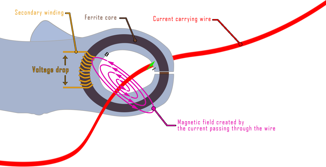
All we need is a transformer core and some copper wire to create our windings. The current passing through the measured wire will create a magnetic field around it as the electromagnetic law tells us. Thanks to the ferrite core of the clamp, this magnetic field will be directed through the this ferrite core. Since the current is an AC current, the magneti flux will change and this will result in a current induced in to the secondary winding as we can see in the photo above. If a current is induced, there will be a voltage drop between the two ends of the winding. We could then measure that voltage drop using our oscilloscope.
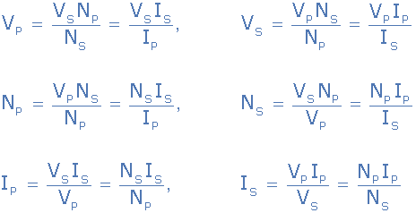
The voltage on the secondary output is equal to the voltage on the primary multiplied by the ratio between the current on the primary by the one in the secondary. Let's say we don't know any of this values. But using an AC current multimeter we control the current through the measured wire and at the same time the output voltage on the oscilloscope. We make a few measurements and we create a graph in order to know the clamp scale.
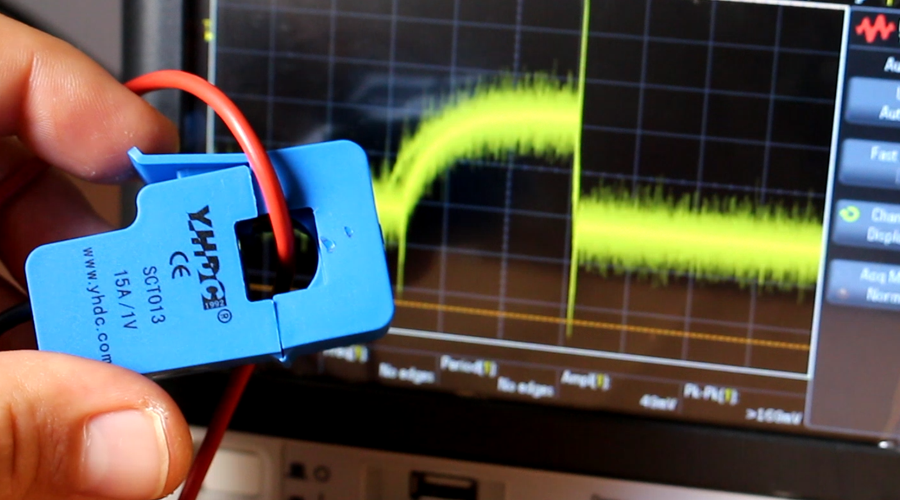
You could buy this kind of module directly winded for a few dollars just like this (photo belwo). This module already gives us then scale of the output voltage of 15A per volt. So, we should have 100mV for a 1,5A current passing trough this wire. I connect this transformer to the oscilloscope and apply a AC signal trough my wire. There you go, here I have my AC current on my oscilloscope. Quite easy right.
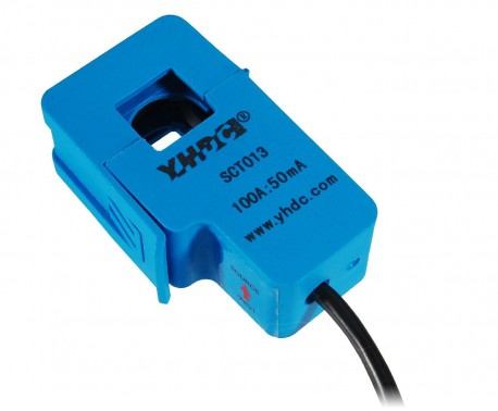
If we build our own transformer we should be careful when calculating the scale depending of the number of windings that we made and knowing that the primary winding will be just one since there will be just one wire passing through the core. But if I apply a DC current to this circuit I’ll have noting on my oscilloscope. That’s because current is induced into the transformer only on changes of the magnetic flux. So, a constant magnetic field won’t induce current into the winding so the output will be 0.
1.1 Build the AC current clamp
BNC female connector LINK eBay
Transformer clamp LINK eBay
10pF capacitor LINK eBay
9m ohms resistor LINK eBay
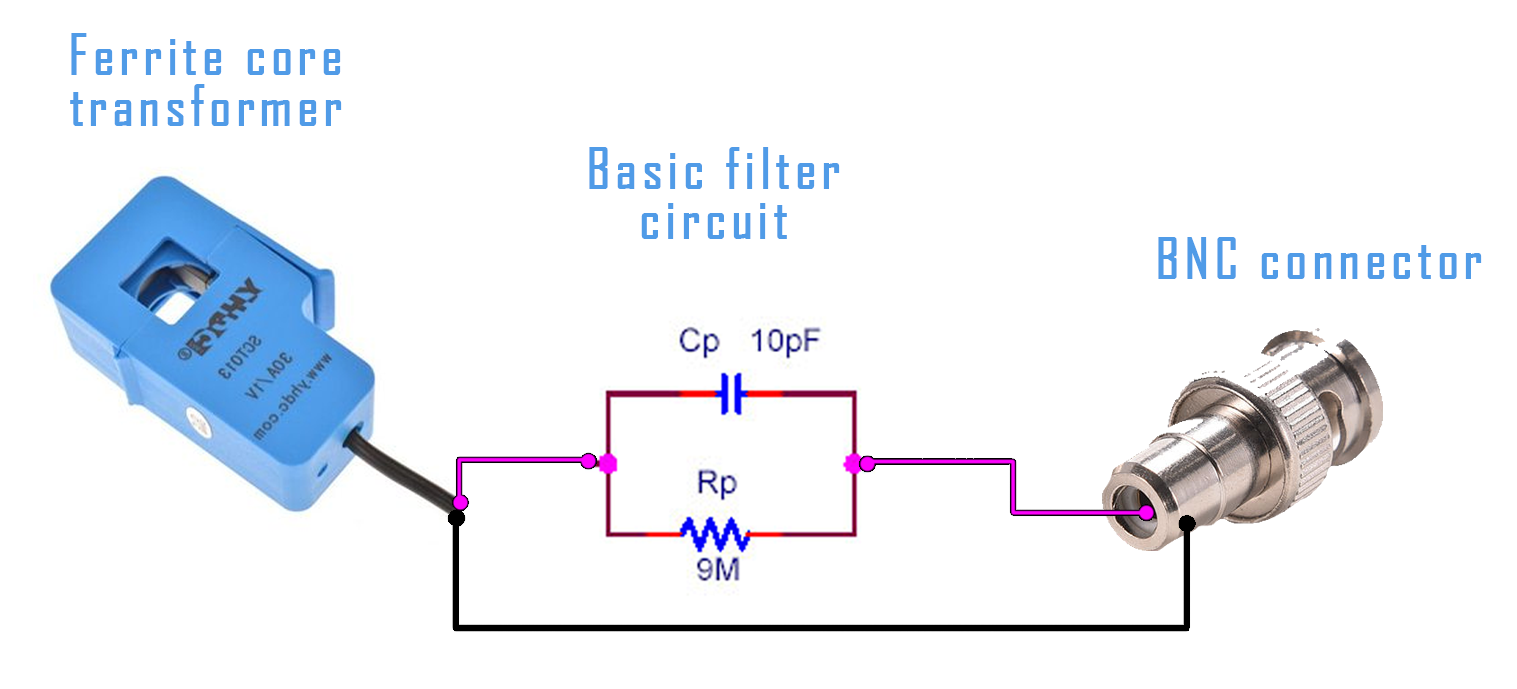
Download the schematic here:
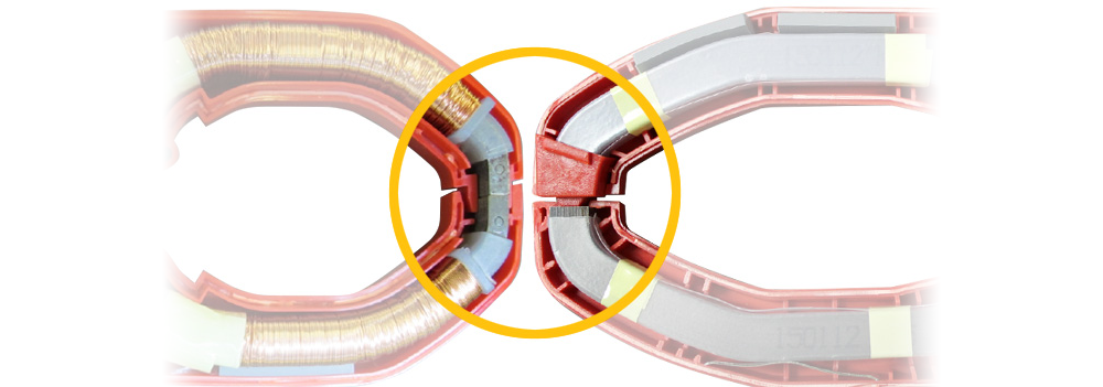
2.0 DC current clamp
So, a constant magnetic field won’t induce current into the winding so the output will be 0. So how we could measure and observe DC current? In this type of probe we will also use a ferrite core that will carry the magnetic field. The core is provided with an air gap that will hold a sensor, in this case a hall-sensor, which measures the magnetic flux in the core. So now we don’t need an AC current anymore since we could directly measure the magnetic flux value. The current in the primary wire, which is the measured wire, will magnetize the core. This magnetic field is measured with the sensor.