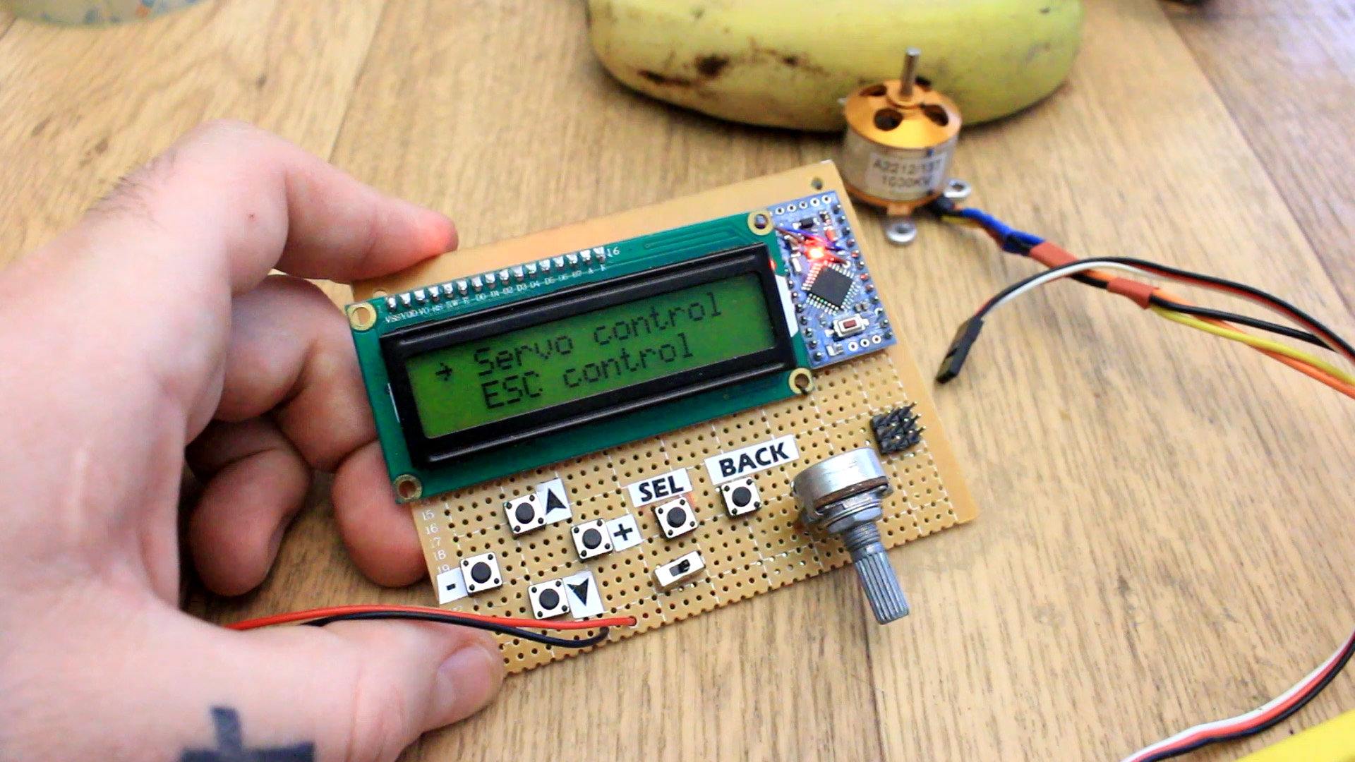

This is a servo or ESC tester. Both of this components work with PWM signals that have a specific range. Usually for servos taht range is between 1000 and 2000us where this range is the width of the PWM signal pulse. By changing this width we change the angle of the servo or the speed of an ESC. In order to haev a precise control of this PWM signal I've made this tester modulw with Arduino. This could also calibrate the ESC to a desired range.
The schematic is very simple. Just the Arduino connected to the i2c module of the LCD. Then we have a potentiometer, 6 push buttons and 3 pins for the PWM output, 5V and GND. We also have a sliding switch to turn the board on and off by connecting the 9V battery.
I mount everything on a drilled PCB. See the part list above in order to know all taht you need. The LCD on one corner and the push buttons just below of that. On the right side I have the Arduino and the PWM pin output that will go to the ESC or the servo. Sliding switch in the middle to turn taht on and off.

The code is made to have 3 modes, for servo, ESC and to calibrate the ESC. Make sure you also install the needed library for the i2c liquid crystal library. The entire code is just a menu with different levels, up to 17. On each level we can select something. We generate the width of the PWM with the potentiometer or with the push buttons. In case of the servo it will be displayed on the screen as degrees from 0 to 180. For ESC it will be in microseconds.
//LCD config
#include <Wire.h>
#include <LiquidCrystal_I2C.h>
LiquidCrystal_I2C lcd(0x3f,20,4);  //sometimes the LCD adress is not 0x3f. Change to 0x27 if it dosn't work.
//inputs/outputs
int left = 2;
int right = 4;
int up = 5;
int down = 6;
int sel = 7;
int back = 8;
int pot = A0;
int pwm = 9;;
You can change the maximum and minimum limits of the signal which usually is from 1000 to 2000us. You can do that in the code or with the menu on the LCD. With the ESC calibration mode, follow the instructions on the LCD to calibrate your ESC to the desired range.