Make sure you mount the schenatic as before. Downlaod the code and uplaod it to the Arduino. Read all the comments in the code to understand more. The code is simple. Remember to install the i2c liquid crystal library and the MAX 66 75 in order to be able to compile this code.
In short words, it goes like this. The interruption on digital pin D8 will detect the zero cross of the main AC signal. Next, we create the PID value and map that from 1 microsecondsv to 7.4 milliseconds and that will be the delay between the zero-cross detection to the firing angle pulse. The rest of the code is for the push buttons read, measure the temperature and fix the setpoint with the buttons. Compile and upload.
This is just the setup loop from the Full Code
void setup() {
  //Define the pins
  pinMode (firing_pin,OUTPUT);
  pinMode (zero_cross,INPUT);
  pinMode (increase_pin,INPUT);
  pinMode (decrease_pin,INPUT);
  PCICR |= (1 << PCIE0);    //enable PCMSK0 scan
  PCMSK0 |= (1 << PCINT0);  //Set pin D8 (zero cross input) trigger an interrupt on state change.
  PCMSK0 |= (1 << PCINT3);  //Set pin D11 (increase button) trigger an interrupt on state change.
  PCMSK0 |= (1 << PCINT4);  //Set pin D12 (decrease button) trigger an interrupt on state change.
  lcd.init();       //Start the LC communication
  lcd.backlight();  //Turn on backlight for LCD
}
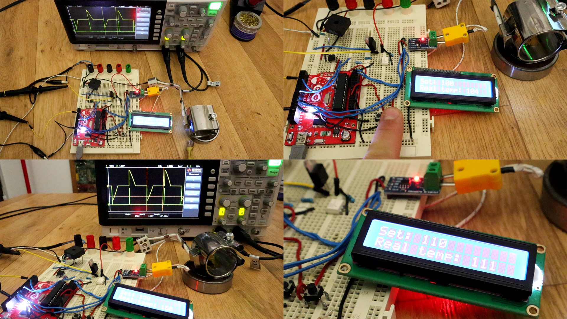
So, there you have it. I could now set the temperature and it will stay there thanks to the PID control. The temperature sometimes has 2 or 3 degrees error but for now that is a good result. In my case, the setpoint step is 5 degrees but you could change that in the code of you want.