


This code is for the schematic.
/* Tranmsitter code for the Arduino Radio control with PWM output
* Install the NRF24 library to your IDE
* Upload this code to the Arduino UNO, NANO, Pro mini (5V,16MHz)
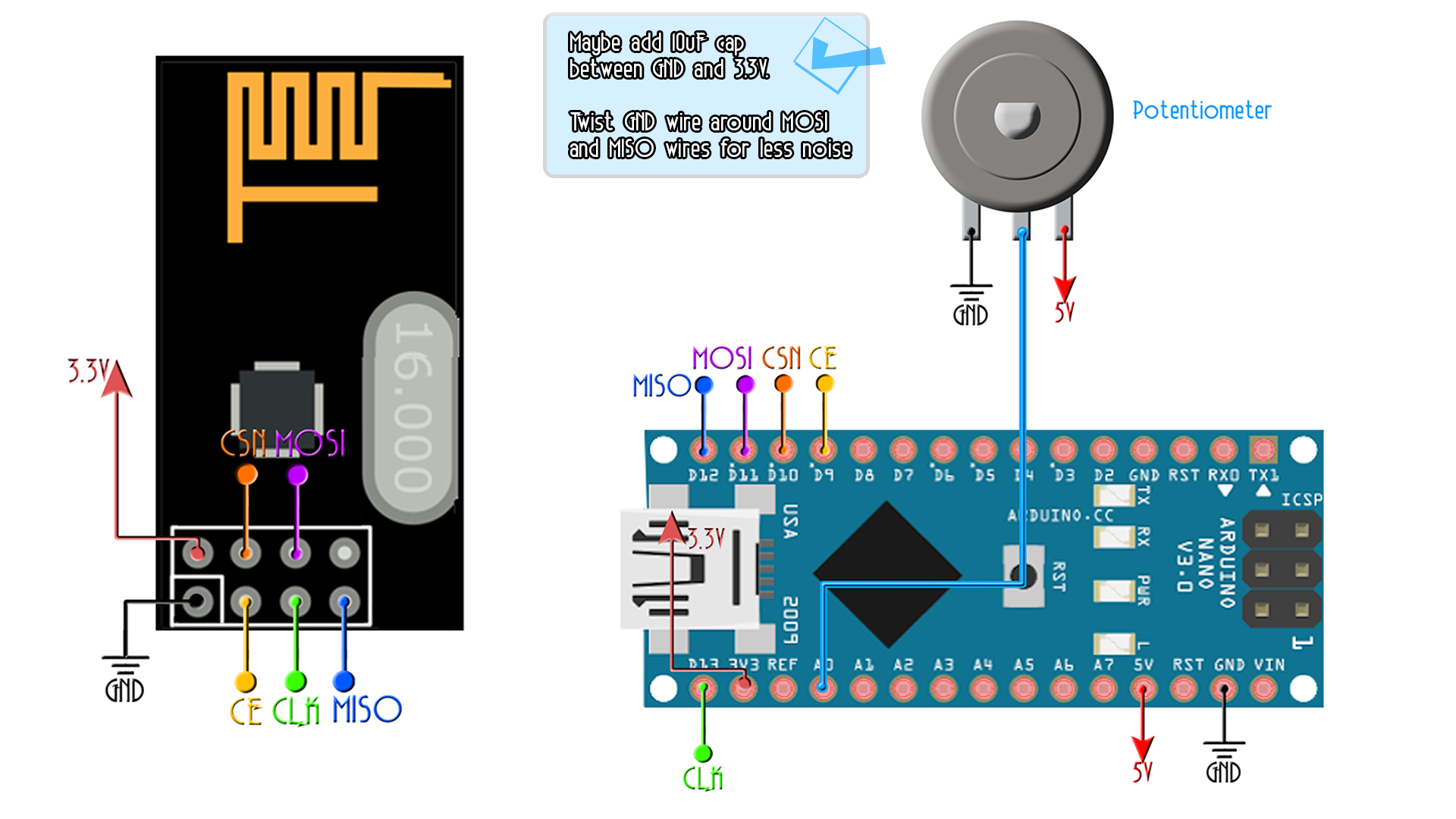
* Connect a NRF24 module to it:
Module // Arduino UNO,NANO
GND -> GND
Vcc -> 3.3V
CE -> D9
CSN -> D10
CLK -> D13
MOSI -> D11
MISO -> D12
This code transmits 1 channels with data from pins A0 POTENTIOMETER
Please, like share and subscribe : https://www.youtube.com/c/ELECTRONOOBS
*/
#include <SPI.h>
#include <nRF24L01.h>
#include <RF24.h>
const uint64_t my_radio_pipe = 0xE8E8F0F0E1LL; //Remember that this code should be the same for the receiver
RF24 radio(9, 10);
// The sizeof this struct should not exceed 32 bytes
struct Data_to_be_sent {
byte ch1;
};
Data_to_be_sent sent_data;
void setup()
{
radio.begin();
radio.setAutoAck(false);
radio.setDataRate(RF24_250KBPS);
radio.openWritingPipe(my_radio_pipe);
sent_data.ch1 = 127;
}
/**************************************************/
void loop()
{
/*If your channel is reversed, just swap 0 to 255 by 255 to 0 below
EXAMPLE:
Normal: data.ch1 = map( analogRead(A0), 0, 1024, 0, 255);
Reversed: data.ch1 = map( analogRead(A0), 0, 1024, 255, 0); */
sent_data.ch1 = map( analogRead(A0), 0, 1024, 0, 255);
radio.write(&sent_data, sizeof(Data_to_be_sent));
}