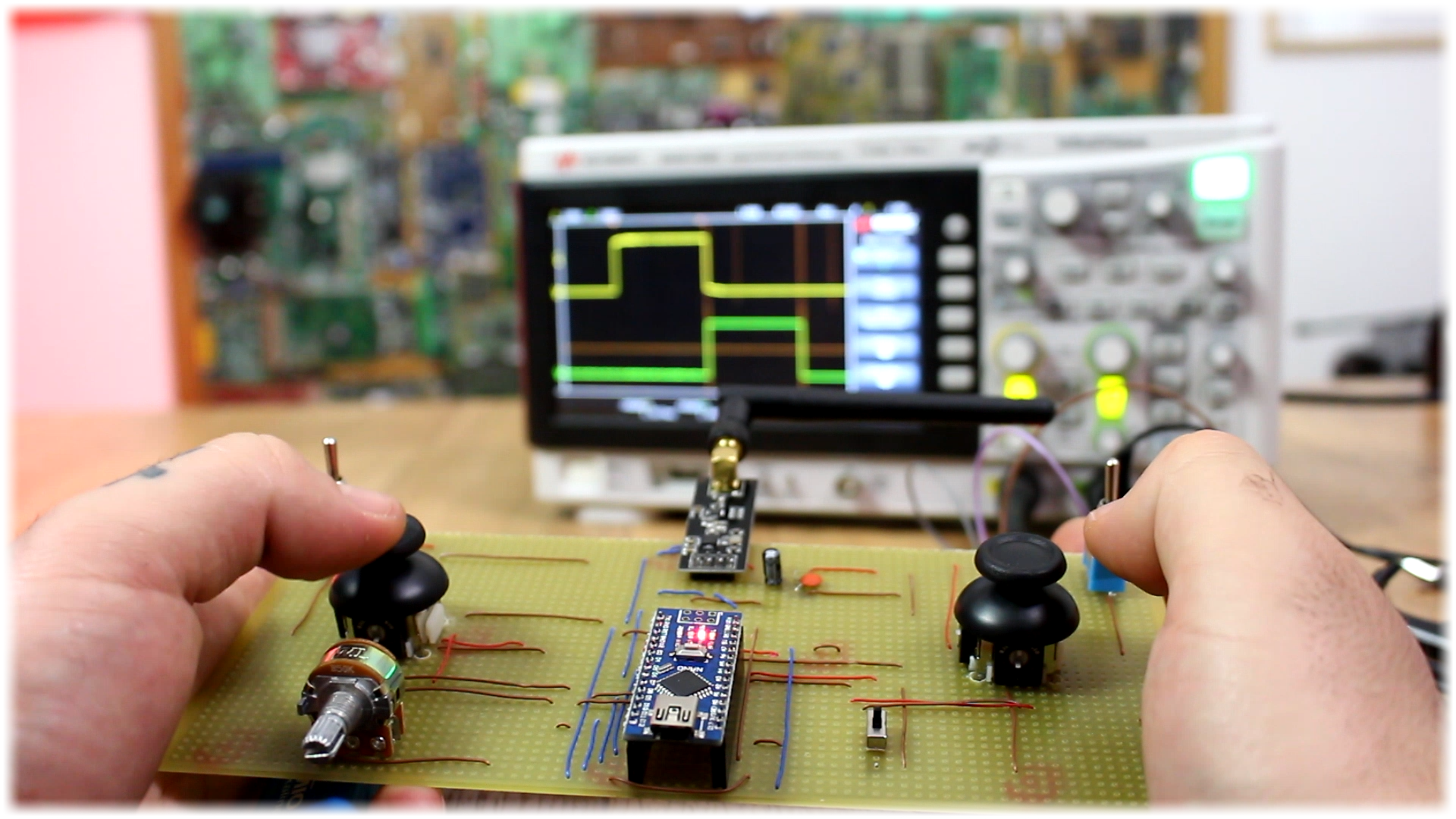
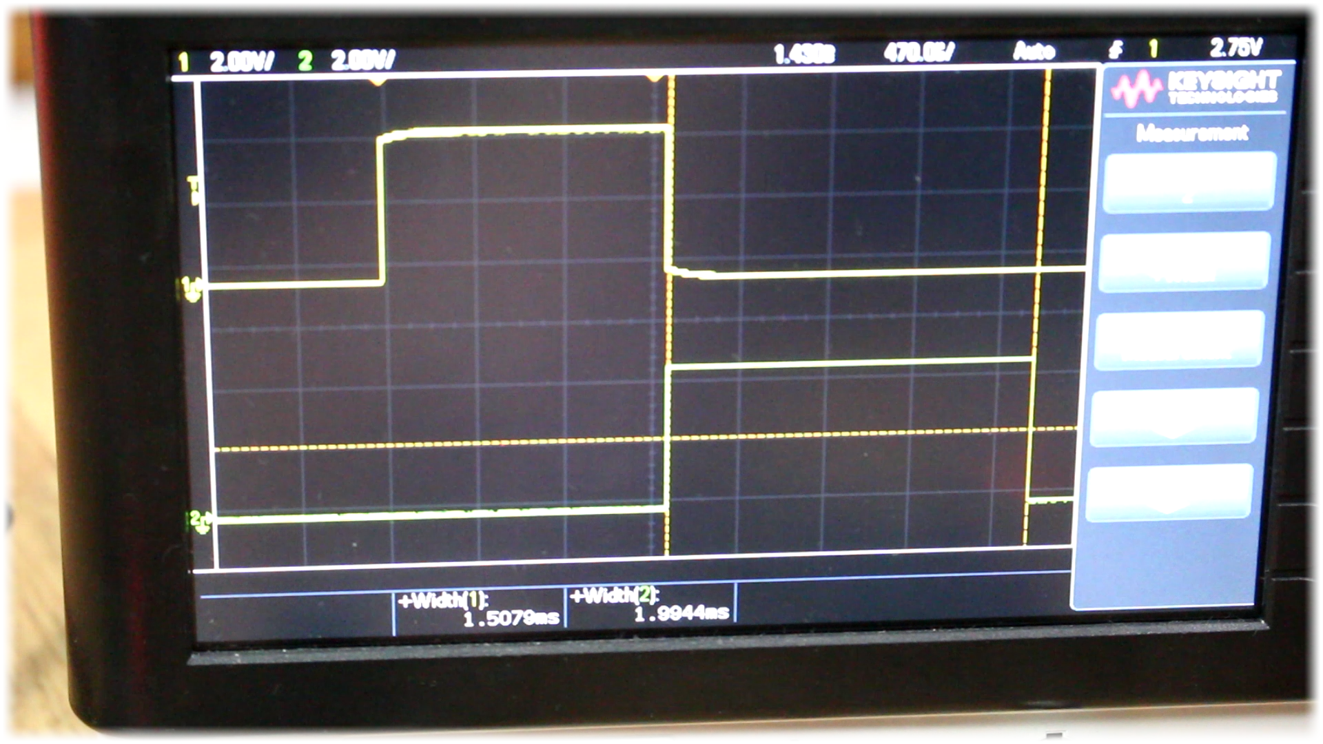
Now upload the codes before to the transmitter and receiver. I connect the battery to the transmitter and power it on. I supply 5V to the receiver and connect two of its channels to my oscilloscope and there you go. I perfectly receive the data from the transmitter. If the values are not exactly in the correct range, which is from 1000 to 2000 microseconds, then go to the received code and change the values here in order to match the minimum and maximum values for each channel.
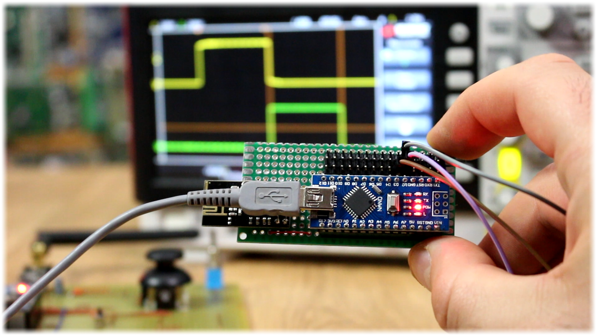
So, there you go my friends. We have build our own radio controller that work’s exactly as any other commercial one but for way less money. You also have the code and schematic for a PPM receiver that will create a 8 channel PPM signal on digital pin D2. The rest of the project is the same.
What is left to do is to probably 3D print a case for this project. Or maybe live it like it is so it should have a more DIY look. Remember that below you have the GERBER files for the transmitter board if you want to send it to JLCPCB and print it. That board has 4 analog channels with two joysticks, and two more digital channels with some sliding switches. You could also add a gyro module and send that data and control RC machines only by moving the controller, but that is for a future project so stay tuned.
Well guys, you have all codes and schematics here on my webpage also on my Patreon page. If you would like to support me, check my Patreon page as well. I would really appreciate that guys. It would help me a lot and I’ll have more and more awesome projects.
I hope that you’ve enjoyed this project.