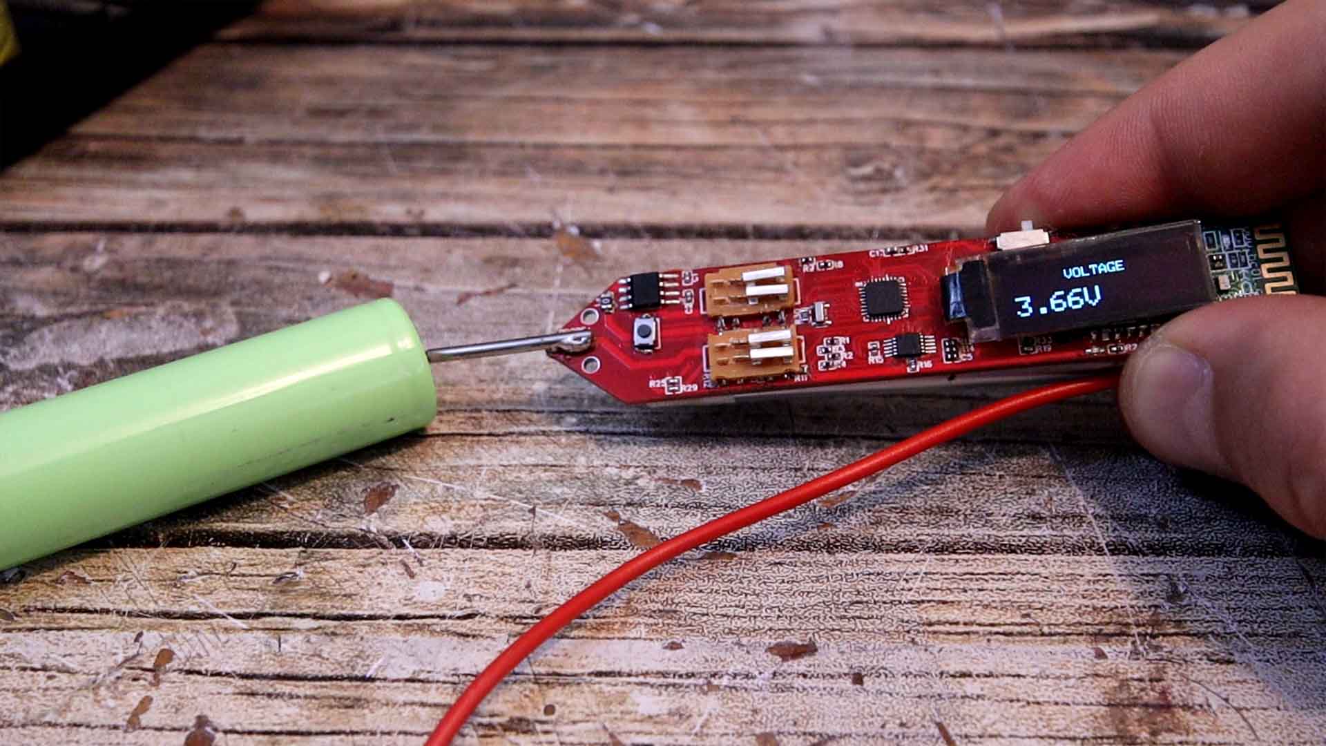
For the probes you will need a cable and two metal pins. I’ll get mine from a cheap multimeter that cost me only 2 dollars. I solder the metal pin on the tip of the multimeter. Then I solder the red wire with the probe on the probe pin on the other side of the PCB. Now we can measure with it, so download from below the final code. Now remove the UART wires. Then we can solder the battery to the battery pads on the back. Slide the on off switch and turn it on. Slide the switch to the right and we are into voltage mode. Since the input for voltage has a voltage divider with a value of 11, this multimeter can measure up to 55V DC. The AC voltage measurement is not ready yet, since the rectifier I’ve used has a voltage drop that is too big and is not even linear…
/* Arduino Two Hand Multimeter V3.2 by ELECTRONOOBS (Voltage, resistance, capacitance, inductance, current, etc) */

/////////////////////////////Library for ADS1115 ADC//////////////////////////////////
#include <Adafruit_ADS1015.h>       //Download here: https://www.electronoobs.com/eng_arduino_Adafruit_ADS1015.php
Adafruit_ADS1115 ads(0x48);
//////////////////////////////////////////////////////////////////////////////////////

////////////////////////OLED 64x124 display with i2c//////////////////////////////////
//OLED screen libraries
#include <Adafruit_GFX.h>           //Download here: https://www.electronoobs.com/eng_arduino_Adafruit_GFX.php
#include <Adafruit_SSD1306.h>       //Download here: https://www.electronoobs.com/eng_arduino_Adafruit_SSD1306.php
#define OLED_RESET 11
Adafruit_SSD1306 display(OLED_RESET);
//////////////////////////////////////////////////////////////////////////////////////


//Define Inputs Outputs
int CapAnalogPin = A0;
int Vcc_read = A1;
int CapAnalogPin2 = A2;
int mode_selector = A3;           //my analog values were: 1023, 675, 405, 285
int Battery = A6;
int D2 = 2;
int D3 = 3;                       //Pins for resistance mode
int D4 = 4;                       //Pins for resistance mode
int D5 = 5;                       //Pins for resistance mode
int Induct_OUT = 6;               //Pin for pulse for inductance mode
int D7 = 7;                       //For voltage mode, divider for set to GND
int D8 = 8;                       //Pins for resistance mode
int Induct_IN = 9;
int Push_button = 10;
int chargePin = 11;
int D12 = 12;
int dischargePin = 13;


/////////////////////Variables/////////////////////
int mode = 4;
bool Push_button_state = true;
bool switch_once = false;

//Voltage mode
float VoltageReadOffset = 0.0;
float Voltage = 0.0;
float Volt_ref = 0;

//Resistance mode
float R2_1 = 2600;    //In ohms
float R2_2 = 18.7;    //In K ohms
float R2_3 = 465;     //in K ohms
int Res_Offset = 0;
bool conductivity = true;

//Capacitance mode
unsigned long startTime;
unsigned long elapsedTime;
float microFarads;
float nanoFarads;
#define resistorValue  10800.00F  //Remember, we've used a 10K resistor to charge the capacitor
bool cap_scale = false;
//Small scale
const float IN_STRAY_CAP_TO_GND = 56.88;
const float IN_CAP_TO_GND  = IN_STRAY_CAP_TO_GND;
const float R_PULLUP = 34.8;
const int MAX_ADC_VALUE = 1023;

//Inductance mode
double pulse, frequency, Induct_cap, inductance;

//Current mode
float Sensibility = 0.185;                      //Given by the ACS712 datasheet but tweeked a bit


//Frequency mode
unsigned long ontime;
unsigned long offtime;
unsigned long the_period;
float the_frequency;
float the_capacitance;


void setup() {
  pinMode(mode_selector, INPUT);
  pinMode(Push_button, INPUT_PULLUP);
  pinMode(Battery, INPUT);


  Serial.begin(9600);

  ads.setGain(GAIN_TWOTHIRDS);        //+/- 6.144V  1 bit = 0.1875mV (default)
  ads.begin();                        //Start the communication with the ADC

  display.begin(SSD1306_SWITCHCAPVCC, 0x3C);  // initialize with the I2C addr 0x3C (for the 128x32 or 64 from eBay)
  delay(200);
  display.clearDisplay();             //Clean the buffer
  display.setTextColor(WHITE);
  display.display();                  //Send data to screen
  delay(200);

  set_all_inputs();
}

void loop() {

  ////////////////////////////MODE DETECTOR//////////////////////////////
  analogReference(DEFAULT);
  int val = analogRead(mode_selector);
  Serial.println(mode);
  //Serial.println(val);
  if(val < 500){
    //Serial.println("Voltage");
    mode = 1;
    switch_once = false;
  }

  else if(val > 500 && val < 800){
    if(!switch_once){
      mode = 2;
      set_all_inputs();
      set_resistance_pins();
      switch_once = true;
      delay(100);
    }
    if(!digitalRead(Push_button) && Push_button_state){
      Push_button_state = false;
      set_all_inputs();
      mode++;
      if(mode > 5){
        mode = 2;
      }
      delay(10);
    }

    else if(digitalRead(Push_button) && !Push_button_state){
      Push_button_state = true;
    }
  }

  else if(val > 800){
    //Serial.println("Current");
    mode = 6;
    switch_once = false;
  }

  ///////////////////////////////////////////////////////////////////////


  ////////////////////////////////MODE 1 VOLTAGE//////////////////////////////////
  if( mode == 1 ){
    pinMode(D12,OUTPUT);
    pinMode(D7,OUTPUT);
    digitalWrite(D12,LOW);
    digitalWrite(D7,LOW);
    float adc; // Leemos el ADC, con 16 bits
    adc = ads.readADC_Differential_0_1();
    //adc = ads.readADC_SingleEnded(0);
    Voltage = 11 * (adc * 0.1875)/1000 + VoltageReadOffset;
    //I've used a 1K and 10K divider so outpout is 1/11 that's why
    //we multiply voltage by  11
    //Serial.print(Voltage, 2);
    //Serial.println(" Volts");
    display.clearDisplay();
    display.setTextSize(1);
    display.setCursor(0,0);
    display.print("       VOLTAGE");    //Print text with line jump;

    display.setTextSize(2);
    display.setCursor(5,16);            //Move 16 pixels downwards and 5 to the right
    display.print(Voltage);
    display.print("V");
    display.display();


    delay(10);
  }
  ////////////////////////////////MODE 1 VOLTAGE//////////////////////////////////


  ////////////////////////////////MODE 2 RESISTANCE//////////////////////////////////
  if( mode == 2 ){
    float Battery_read = read_battery(20);
    float vcc = (Battery_read * (1.1/1023.0)) / 0.167863707;

    Serial.print("Vcc: ");
    Serial.println(vcc);


    pinMode(D4,INPUT);
    pinMode(D5,INPUT);
    pinMode(D8,OUTPUT);
    digitalWrite(D8,LOW);
    delay(100);


    float adc2;
    float res;

    /*int res_loop = 0;
    while(res_loop < 10)
    {
      adc2 = ads.readADC_SingleEnded(2);
      Voltage = Voltage + (adc2 * 0.1875)/1000;
      res_loop = res_loop + 1;
    }
    Voltage = Voltage/10;    */
    //adc2 = read_ADC2(5);

    adc2 = ads.readADC_SingleEnded(2);
    Voltage = (adc2 * 0.1875)/1000;
    res = ((R2_1*vcc)/Voltage) - R2_1 - Res_Offset;


    if(res < 0){
      display.clearDisplay();
      display.setTextSize(1);
      display.setTextColor(WHITE);
      display.setCursor(0,0);
      display.print("     RESISTANCE");    //Print text with line jump;
      display.setTextSize(1);
      display.setCursor(5,16);            //Move 16 pixels downwards and 5 to the right
      display.print("  INSERT RESISTOR");
      display.display();
    }

    else if(res > 0 && res < 2000){
      display.clearDisplay();
      display.setTextSize(1);
      display.setTextColor(WHITE);
      display.setCursor(0,0);
      display.print("     RESISTANCE");    //Print text with line jump;
      display.setTextSize(2);
      display.setCursor(5,16);            //Move 16 pixels downwards and 5 to the right
      display.print(res,0);
      display.print(" Ohms");
      display.display();
    }

    else if(res < 20000){
      pinMode(D8,INPUT);
      pinMode(D4,OUTPUT);
      pinMode(D5,INPUT);
      digitalWrite(D4,LOW);
      delay(5);

      adc2 = ads.readADC_SingleEnded(2);
      Voltage = (adc2 * 0.1875)/1000;
      res = ((R2_2*vcc)/Voltage) - R2_2;

      display.clearDisplay();
      display.setTextSize(1);
      display.setTextColor(WHITE);
      display.setCursor(0,0);
      display.print("     RESISTANCE");    //Print text with line jump;
      display.setTextSize(2);
      display.setCursor(5,16);            //Move 16 pixels downwards and 5 to the right
      display.print(res,1);
      display.print(" K");
      display.display();
    }
    else if(res > 20000){
      pinMode(D5,OUTPUT);
      digitalWrite(D5,LOW);
      pinMode(D8,INPUT);
      pinMode(D4,INPUT);
      delay(5);
      adc2 = ads.readADC_SingleEnded(2);
      Voltage = (adc2 * 0.1875)/1000;
      res = ((R2_3*vcc)/Voltage) - R2_3;
      if(res < 2000){
        display.clearDisplay();
        display.setTextSize(1);
        display.setTextColor(WHITE);
        display.setCursor(0,0);
        display.print("     RESISTANCE");    //Print text with line jump;
        display.setTextSize(2);
        display.setCursor(5,16);            //Move 16 pixels downwards and 5 to the right
        display.print(res,1);
        display.print(" K");
        display.display();
      }
      else{
        display.clearDisplay();
        display.setTextSize(1);
        display.setTextColor(WHITE);
        display.setCursor(0,0);
        display.print("     RESISTANCE");    //Print text with line jump;
        display.setTextSize(1);
        display.setCursor(5,16);            //Move 16 pixels downwards and 5 to the right
        display.print("  INSERT RESISTOR");
        display.display();
      }
    }
    delay(10);
  }//end mode 2
  ////////////////////////////////MODE 2 RESISTANCE//////////////////////////////////


  ///////////////////////////////MODE 3 CAPACITANCE//////////////////////////////////
  if( mode == 3 ){
    analogReference(DEFAULT);
    pinMode(CapAnalogPin,INPUT);
    pinMode(CapAnalogPin2, OUTPUT);
    pinMode(chargePin, OUTPUT);

    digitalWrite(CapAnalogPin2, LOW);
    digitalWrite(chargePin, HIGH);
    startTime = micros();

    while(analogRead(CapAnalogPin) < 645){
      if(!digitalRead(Push_button)){
        break;
        }
      }    //Get up to 63% of 1024

    elapsedTime= micros() - startTime;
    microFarads = ((float)elapsedTime / resistorValue) - 1.141;

    if (microFarads > 1)
    {
      display.clearDisplay();
      display.setTextSize(1);
      display.setTextColor(WHITE);
      display.setCursor(0,0);
      display.print("     CAPACITANCE");    //Print text with line jump;
      display.setTextSize(2);
      display.setCursor(5,16);              //Move 16 pixels downwards and 5 to the right
      display.print(microFarads,1);
      display.print(" uF");
      display.display();
      delay(100);
    }

    else
    {
      nanoFarads = microFarads * 1000.0;
      display.clearDisplay();
      display.setTextSize(1);
      display.setTextColor(WHITE);
      display.setCursor(0,0);
      display.print("     CAPACITANCE");    //Print text with line jump;
      display.setTextSize(2);
      display.setCursor(5,16);              //Move 16 pixels downwards and 5 to the right
      display.print(nanoFarads,1);
      display.print(" nF");
      display.display();
      delay(100);
    }

    digitalWrite(chargePin, LOW);
    pinMode(dischargePin, OUTPUT);
    digitalWrite(dischargePin, LOW);        //discharging the capacitor
    while(analogRead(CapAnalogPin) > 0){}   //This while waits till the capaccitor is discharged
    pinMode(dischargePin, INPUT);           //this sets the pin to high impedance
    //Serial.println("Discharging");

  }
  ///////////////////////////////MODE 3 CAPACITANCE//////////////////////////////////


  ////////////////////////////////MODE 4 INDUCTANCE//////////////////////////////////
  if( mode == 4 )  {
    pinMode(A7, OUTPUT);
    digitalWrite(A7, LOW);
    pinMode(CapAnalogPin, OUTPUT);  //A0
    digitalWrite(CapAnalogPin, LOW);

    display.clearDisplay();
    display.setTextSize(1);
    display.setTextColor(WHITE);
    display.setCursor(0,0);
    display.print("     INDUCTANCE");    //Print text with line jump
    display.display();

    pinMode(Induct_OUT, OUTPUT);

    pinMode(Induct_IN, INPUT);

    digitalWrite(Induct_OUT, HIGH);
    delay(5);                               //give some time to charge inductor.
    digitalWrite(Induct_OUT,LOW);
    delayMicroseconds(100);                 //make sure resination is measured
    pulse = pulseIn(Induct_IN,HIGH,5000);   //returns 0 if timeout
    if(pulse > 0.1)                         //if a timeout did not occur and it took a reading:
    {
      //#error insert your used capacitance value here. Currently using 2uF. Delete this line after that
      Induct_cap = 2.E-6;                                                   // - insert value here

      frequency = 1.E6/(2*pulse);
      inductance = 1./(Induct_cap*frequency*frequency*4.*3.14159*3.14159);  //one of my profs told me just do squares like this
      inductance *= 1E6;                                                    //note that this is the same as saying inductance = inductance*1E6

      display.setTextSize(2);
      display.setCursor(5,16);              //Move 16 pixels downwards and 5 to the right
      display.print(inductance,1);
      display.print(" uH");
      display.display();
      delay(100);
    }
  }//end mode 4
  /////////////////////////////END MODE 4 INDUCTANCE/////////////////////////////////


  ////////////////////////////////MODE 5 FREQUENCY//////////////////////////////////
  if( mode == 5 ){
    noInterrupts();
    pinMode(A2,INPUT);
    ontime = pulseIn(A2,HIGH);
    offtime = pulseIn(A2,LOW);
    interrupts();

    the_period = ontime+offtime;
    the_frequency = 1000000.0/the_period;
    the_capacitance = 1 * (1.4427*1000000000)/(2545*the_frequency);   //calculating the Capacitance in nF
    display.clearDisplay();
    display.setTextSize(1);
    display.setTextColor(WHITE);
    display.setCursor(0,0);
    display.print("     FREQUENCY");    //Print text with line jump;
    display.setTextSize(2);
    display.setCursor(5,16);              //Move 16 pixels downwards and 5 to the right
    display.print(the_frequency,0);
    display.print(" Hz");
    display.display();
    delay(100);
  }
  ////////////////////////////////MODE 5 FREQUENCY/////////////////////////////////


  /////////////////////////////MODE 6 CURRENT/////////////////////////////////
  if( mode == 6 )
  {
    set_all_inputs();
    int read_loop = 0;
    float Sens_volt = 0;
    while(read_loop < 100)
    {
      float adc3; // Leemos el ADC, con 16 bits
      adc3 = ads.readADC_SingleEnded(3);
      Sens_volt = Sens_volt + ((adc3 * 0.1875)/1000);
      read_loop = read_loop + 1;
    }
    Sens_volt = Sens_volt/100;
    Serial.println(Sens_volt,5);
    float curr =  ((Sens_volt - 2.006)/Sensibility)*1000; //


    display.clearDisplay();
    display.setTextSize(1);
    display.setTextColor(WHITE);
    display.setCursor(0,0);
    display.print("      CURRENT");    //Print text with line jump;

    display.setTextSize(2);
    display.setTextColor(WHITE);
    display.setCursor(5,16);              //Move 16 pixels downwards and 5 to the right
    display.print(curr,0);
    display.println(" mA");
    display.display();
  }
  /////////////////////////////MODE 5 CURRENT/////////////////////////////////


}//End of void loop


void set_all_inputs(){
  pinMode(CapAnalogPin,INPUT);              //A0
  pinMode(Vcc_read,INPUT);                  //A1
  pinMode(CapAnalogPin2,INPUT);             //A2
  //A3 is for mode selector (already input) //A3
  //A4 is for SDA                           //A4
  //A5 is for SCL                           //A5
  //A6 is for battery read (already input)  //A6
  pinMode(A7,INPUT);                        //A7
  pinMode(D2,INPUT);                        //D2
  pinMode(D3,INPUT);                        //D3
  pinMode(D4,INPUT);                        //D4
  pinMode(D5,INPUT);                        //D5
  pinMode(Induct_OUT,INPUT);                //D6
  pinMode(D7,INPUT);                        //D7
  pinMode(D8,INPUT);                        //D8
  pinMode(Induct_IN,INPUT);                 //D9
  //D10 is push button (already input)      //D10
  pinMode(chargePin,INPUT);                 //D11
  pinMode(D12,INPUT);                       //D12
  pinMode(dischargePin,INPUT);              //D13
}


void set_resistance_pins(){
  pinMode(Vcc_read,OUTPUT);                 //A1
  digitalWrite(Vcc_read,HIGH);              //A1
  pinMode(CapAnalogPin2,OUTPUT);            //A2
  digitalWrite(CapAnalogPin2,HIGH);         //A2
  pinMode(Induct_OUT,OUTPUT);               //D6
  digitalWrite(Induct_OUT,HIGH);            //D6
  pinMode(Induct_IN,OUTPUT);                //D9
  digitalWrite(Induct_IN,HIGH);             //D9
  pinMode(D8,OUTPUT);
  digitalWrite(D8,LOW);
}


float read_battery (int times){
  float bat_read = 0;
  for (int i = 0; i<times; i++){
    ADMUX |= B01000000;
    //We read A6 (MUX6)
    ADMUX |= B00000110;
    ADCSRA |= _BV(ADEN);  // enable the ADC
    delay(10);            // wait for voltages to become stable.
    ADCSRA |= _BV(ADSC);  // Start the ADC
    while (bit_is_set(ADCSRA,ADSC));
    bat_read = bat_read + (ADCL | (ADCH << 8));
  }
  float Bat_volt = bat_read/times;
  analogReference(DEFAULT);
  return Bat_volt;
}


float read_ADC2 (int times){
  float ADC2_READ = 0;
  for (int i = 0; i<times; i++){
    ADC2_READ = ADC2_READ + ads.readADC_SingleEnded(2);
  }
  float ADC2_OUT = ADC2_READ/times;
  return ADC2_OUT;
}