Today I start a new and very interesting video series about IOT or internet of things. We learn how to get from an ESP32 to a cloud database and from the internet back to the ESP. IOT is very common nowadays, and is very interesting. I’ve made such project a few years ago, but I get a ton of questions about that video. That’s because that tutorial was a little bit difficult to follow. And that’s because I was using the ESP8266 and AT commands. Using AT commands the code was very, very long and difficult to follow and most of you guys weren’t able to establi sh a good connection with the servers. Today we start with the ESP32 microcontroller. Is very small, very powerful, very fast because it’s 32 bits and works at 80Mhz, and best of all, it has WIFI included. And to make it all easier, instead of using AT commands, we will use the HTTPclient library from Arduino IDE so the code would be very easy. That’s great, right? Also, different to my previous videos, this method will be a lot more secure because instead of GET method we will use the POST method which uses encrypted data and is a lot more secure. Together with that we will make a website platform and control stuff using the internet. So guys, let’s get started.
The EPS32 microcontroller has WIFI included adn the board is very small and you can get it from HERE . This controller works at 3.3V and to be able to program it we need a basic configuration with some pullups and buttons. This ESP32 development board already has that configuration and a USB connector together with an FTDI programmer IC so we can program it directly. Connect it to your PC and make sure your windows will install the drivers for the FTDI chip which in this case is the CP2102. Let’s make the ESP32 work with Arduino so open your Arduino IDE. Then go to preferences and in the extra URLs you have to paste this link from below.
Now go to tools, boards and click the boards manager. Search for ESP32. Select these boards and click install and as you can see I already have them installed. Now if you go once again to tools, boards, you can see that we can now select between a lot of ESP32 boards. In my case I select this one. ESP32 Dev Module. For the rest of the settings make sure you have the ones below if you're using the same DEV board as I am.
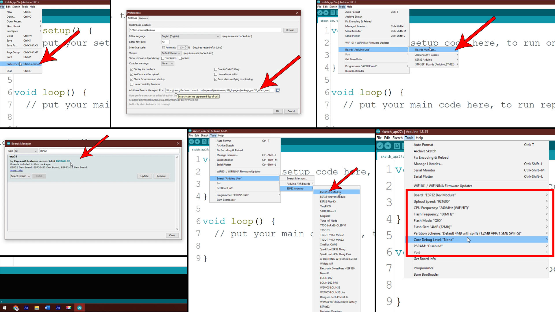
Now I write this simple code where I blink the GPIO 2. This Development board has an LED on that digital pin 2. Select the COM of the ESP32. Then click the upload button but make sure you press and maintain the boot button on the board. When you see the “connecting” message on the Arduino IDE, release the boot button and you will see that the code will get uploaded. Success, we now have a blinking LED so we have successfully uploaded a code to the ESP32 using Arduino and that was part 1.
int LED  = 2;

void setup() {
  pinMode(LED, OUTPUT);
}

void loop() {
  digitalWrite(LED, HIGH);
  delay(1000);
  digitalWrite(LED, LOW);
  delay(1000);
}Let’s go to the next part. For learning is good to use the development board, but for final projects I want to use directly the ESP32 board, because it’s very small and we don't always need the rest of the components. For future project, I’m preparing a PCB which will be part of a very interesting project so stay tuned for that. I want to solder the ESP directly to my PCB. I want the bare minimum, so I will get rid of the USB connector, the FTDI programmer, the boot and the enable buttons, the LEDs and the male pins all round. All I keep are the 3.3V voltage regulator and the pullup resistors. This below is the bare minimum configuration that we need. A pullup resistor on the Enable pin and another one on the GPIO 0 pin or FLASH. To upload the codes I will use an external programmer module like the one below. This costs only 2 dollars and we only need it when we upload the code or making tests.
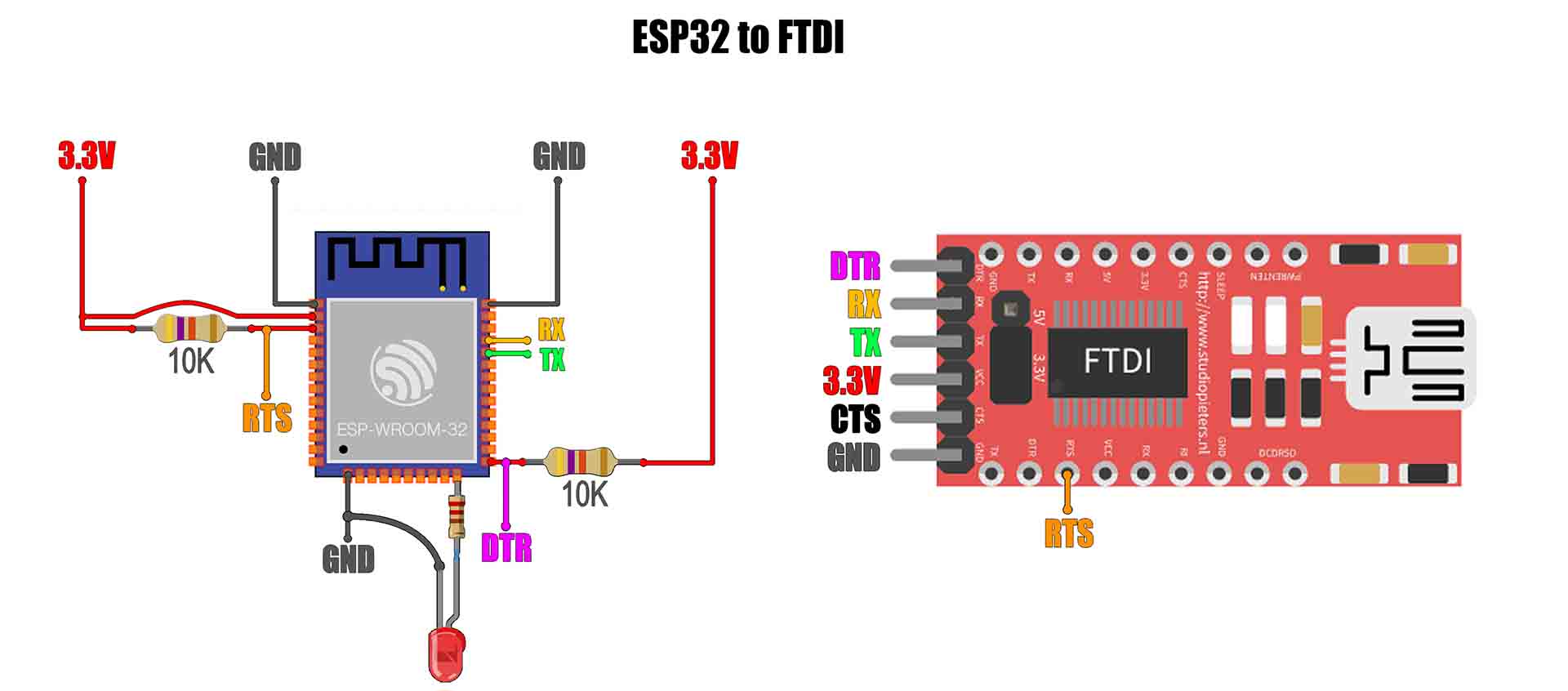
But you see, with the development board we use the boot and enable button to start the uploading process. In this case we don’t have that so we will use the DTR and RTS pins from the FTDI programmer. I solder the small ESP32 to a prototyping board so we can use it easier. I add the pullup resistors. I also have an LED on GIPO2 for tests. Connect the FTDI module like above, RX to TX, TX to RX, DTR pin to the GPIO0 and ther RTS pin to the enable pin. Connect the USB cable. Open Arduino IDE, select the COM and let’s upload the same code as before. There you go, we now have a blinking LED. So the second part is also ready, now we get into the complicated part. Let’s communicate with a server database.
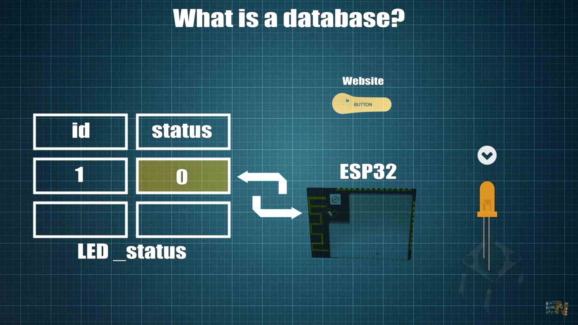
This is a learning tutorial so I will use a free hosting and server which is a bit slow. For that I usually use 000webhost.com A database is just like an Excel file but is on an online server, we call this "the cloud". This database will have columns and rows and we can store data on it. For example we create a simple table and name it LED_status. This will have two columns, one called ID and another one called status and they both have integer values. Then we create a website page with a button. Each time we press this button on our website, we change the status of that LED on the database table from a 1 to a 0 or from a 0 to a 1. The interesting part is when we introduce the ESP32. Because we can connect to the internet with this microcontroller and access this database as well, and read the status value. If it’s a 1 for example, we turn on an LED on the ESP32. If it’s a 0, we turn it off. We can also connect a button to the ESP32 and when we press it we can change the status value on the database from 1 to a 0 or vice versa. Basically, we can control anything from anywhere in the world and that is part of IOT.
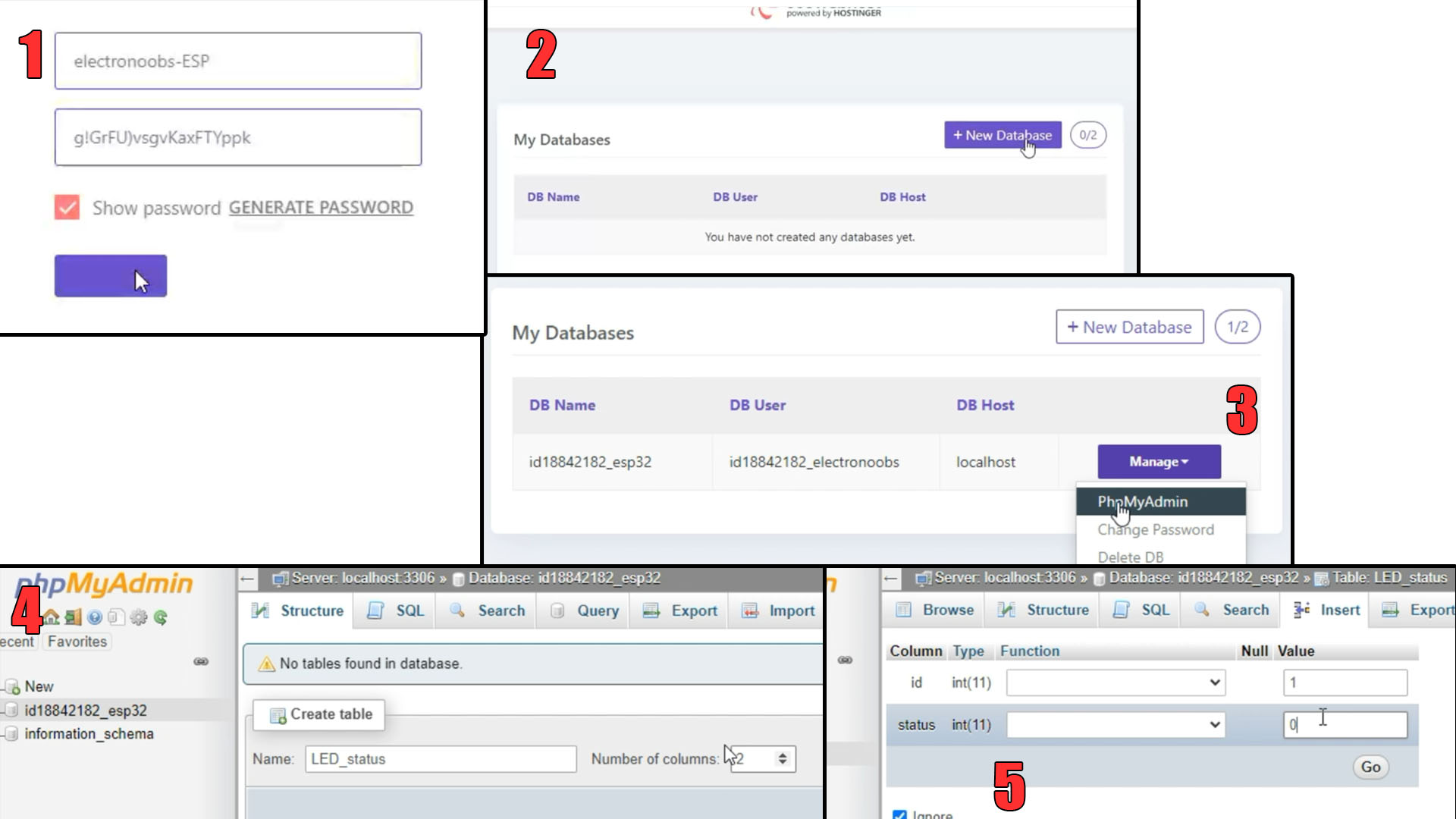
So, go to 000webhost.com or any other hosting provider. Create an account using your email. Once you have the account, create a new website and give it a name (1), in my case I call it "electronoobs-ESP". But because this is a free hosting service, it will add 000webhostapp at the end of the name but that’s not a problem (so it will be https://electronoobs-esp.000webhostapp.com). Once you have your website click manage website, then go to tools and select database manager. Click create a new database (2). Give it a name, a username and a password and click create. Once the creating database process is done, click manage and go to phpMyAdmin (3) and here is where we create our tables. You will see the database is empty so we need to create a new table. I give the name of LED_status and give it 2 columns (4). I name the first column id and the second one status. They are both integers of 11 values. Make the id column to be auto increment and primary. The table is now empty so click the insert button and add a new row (5). I add an ID 1 and the status 0 meaning the LED is turned off. Great, now we have our database.
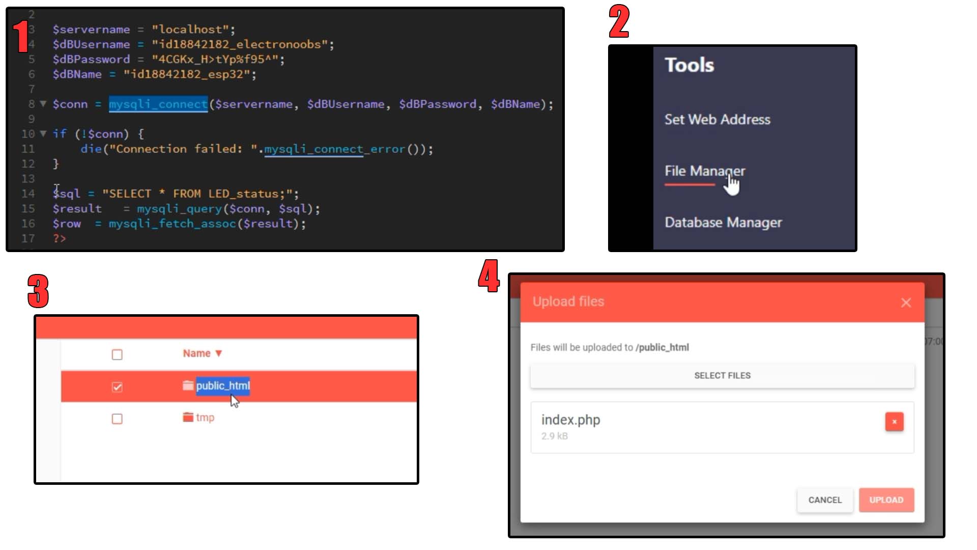
Now we need to create the control website. So for that, you have to download the index.php and the esp32_update.php files from below. You will download a .zip file with all the files for the website fore this project. If you open the index file, you will see that we first connect to the database using the username and password before. You can find these data on the database manager of your website. Copy your username, database name and your password and paste them in the php code on the top lines. And with the next line we make a mySQL connection to the database. With the other lines we read the columns from the LED status table. And then we echo the status value. Let’s upload this index.php file to our website. Click once again manage websites, and click “file manager”. Double click on the public html folder and here is where we must upload our index.php. Click the upload button and I upload the index.php but also the esp32_update.php and two png files.
Download the Arduino code from below. Open Arduino IDE. If you don’t have them, download from below the HTTPserver and the WIFI libraries. Go to sketch, include library, add zip file library, and select one by one the downloaded zip files. In the code, on these lines add the name of your home WIFI and the WIFI password. Then, in the http.begin function, you have to change the website from electronoobs-ESP to your own website. As you can see, this code will communicate with a file that is called esp32_update.php. We've uploaded that file to our website in the previous step.
In the Arduino code as you can see, we make a post action with that variable name, check_LED_status. So, the PHP file, each time it detects that someone makes a post action with this variable name, it will read the status of the LED from the database and echo LED_is_off or LED_is_on. In the Arduino code, we get the response from the website. If the response is LED is off, we make a digital write LOW on digital pin 2 which is where our LED is connected. If the response is LED is ON we make a digital write HIGH on that pin.
//Add WIFI data
const char* ssid = "mywifiname";              //Add your WIFI network name
const char* password =  "12345678";           //Add WIFI password

http.begin("https://electronoobs-esp.000webhostapp.com/esp32_update.php"); //Change this with youd websiteThe toggle control from the website still works. But when I press the push button, as you can see, we change the value of the database. Each time I press the button, I change the value on my website so this process works both ways. I can turn on the LED from the internet or I can change the database values from my ESP32. Now you know how to make a POST action on a database using the ESP32 and get or send data from the microcontroller. In the next video of ESP32 IOT we will create a cool project and control things around our home so stay tuned for that. Now you know how to create an IOT system with the ESP, Arduino code, a simple database and WIFI connection. You can download all the files from electronoobs.com and test them out with your data. Consider giving me a like or comment below. Thanks again and see you later guys. If my videos help you, consider supporting my work on my PATREON or a donation on my PayPal. Thanks again and see you later guys.