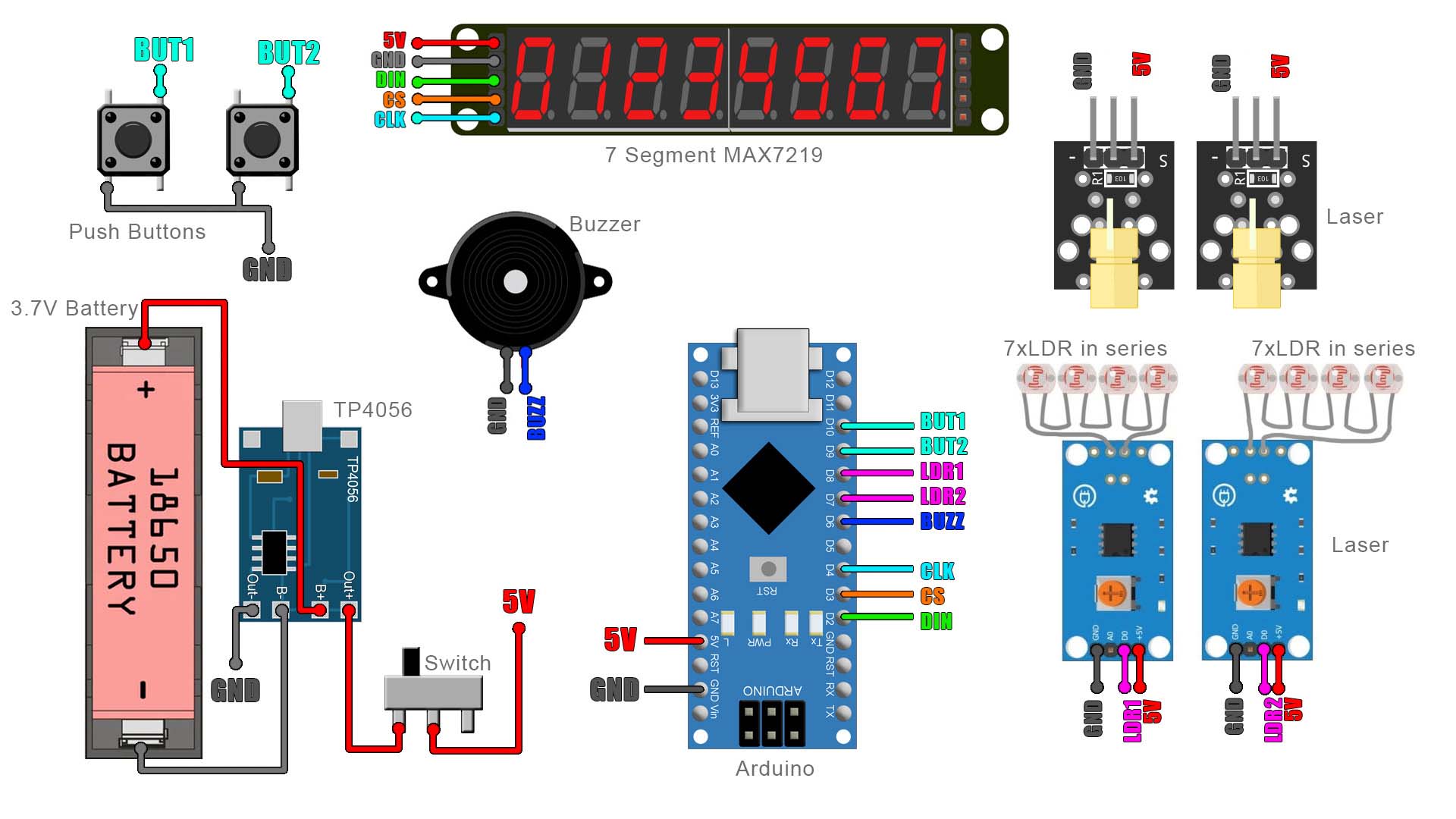
This is the schematic for the project. Just the sensors connected to the Arduino, the battery for supply and the display to show the speed value. First we solder the charger to the battery. Then, between the battery and the circuit I add a switch so we could turn the circuit on and off. This switch will power the Arduino which is connected to the sensors, the buzzer and the display. The 5V connection is actuall 4.2V from the battery but that's enough for the Arduino to work ok. Make all connections as below.