Maybe not a lot of you guys know that the ATmega328 microcontroller has a programmable internal comparator. This could have the positive input connected to pin D6 and the negative inputs connected to any of the inputs A0 to A7 of the Arduino. The output of the comparator could create an interruption and that is very usefull. I've used this comparator for my Arduino ESC project in order to simplify the circuit and code to be faster.
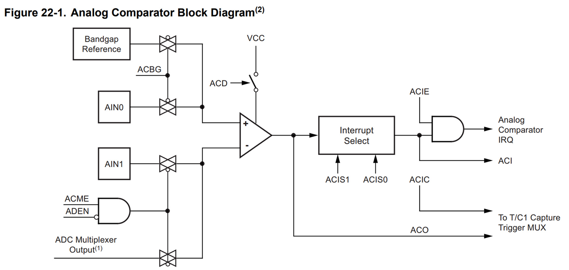
Below we have the blocks diagram from the ATmega328 datasheet. Let me explain it. In the middle there is the programmable comparator. Around it, each part could be configured with some bits taht we will go through one by one. Changing the value of these bits, we can put the comaprator into falling or rising mode detection, to be connected to D6 or not, ot to A0 to A7 and we could read the output value or run an interruption. The bits we need to change are the ACBG, the ACME, ADEN and those two bits ACIS1 and ACIS0. So let's see.
Ok, let's go one by one. First bit you need to change is bit 4 from the ACSR register, which os the bit ACI as you can see below in the table below from this datasheet If we set this bit to 1, the comparator output interrupt is actrive and we can set the rising or falling edge mode woith bits ACIS0 and ACIS1. Som first thing, to enable the interruption and the comparator we set bit ACI to 1 as below. Remember taht in Arduino, when working with registers, we put "0" with an AND (&) operation and we place "1" with an OR (|) opeartion. See code below.
ACSR |= B00010000; //This will set bit 4 of the ACSR register, so bit ACI, to be equal to "1"
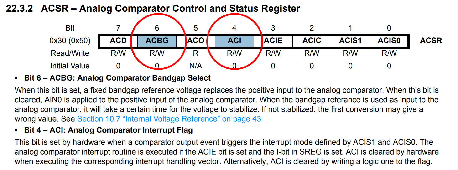
As you can also see in the table above, bit ACBG is bit 6 from the ACSR register of 8 bits. If we read below, this bit controls the positive input of the comparator. If the bit is set to 1, the positive input of the comparator is connected to a constant analog value called bandgap reference as you can see in the block diagram above. When the bit is cleared, so equal to 0, the positive input is connected to AIN0 which is connected to pin D6 of the Arduino. For today example, taht's what we want. So we need to set bit ACBG to 0 so we do ACSR &= B11011111; in order to put bit 6 to 0. In any case, by default, this bit is already 0.
ACSR &= B11011111; //This will set bit 6 of the ACSR register, so bit ACBG, to be equal to "0"
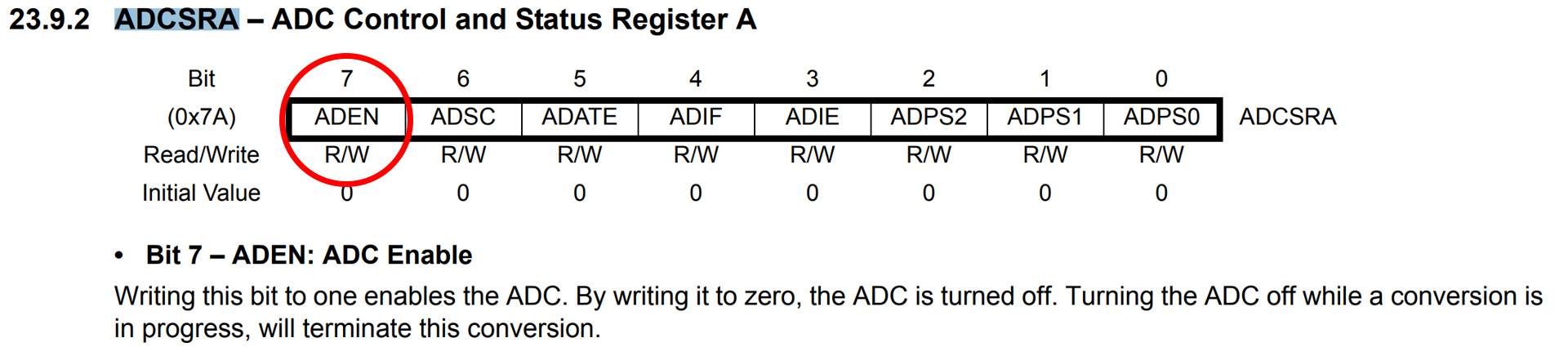
Ok, if you check the block diagram above, with bits ADEN and ACME we can enable and select the negative input of the comparator. This input could be connected to inputs A0 to A7 of the Arduino. But for that, we need to put first ADEN bit to 0 in order to turn off the ADC module. You see, if you use the A0 to A7 pins as inputs for the comparator you can't use them as ADC inputs as well, so we turn off the ADC module. So we need to set bit ADEN to 0 so we do ADCSRA = (0 << ADEN); in order to put bit 7 to 0.
ADCSRA = (0 << ADEN);     /* Set ADEN bit to 0 so we disable the ADC module because
  we use the analog inputs A0 - A7 as negative inputs of the comaprator*/
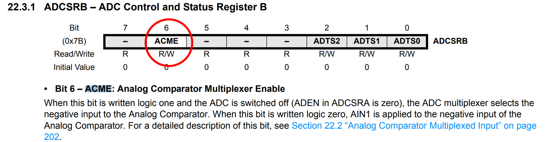
Now we need to set ACME bit to 1 in order to use the ADC multiplexer to selects the negative input to the Analog Comparator. If this bit is 1, we can use the MUX and select between inputs A0 to A7. So we need to set bit ACME to 1 so we do ADCSRB = (1 << ACME); in order to put bit 6 to 1.
ADCSRB = (1 << ACME); // Enable the MUX selector for negative input of comparator
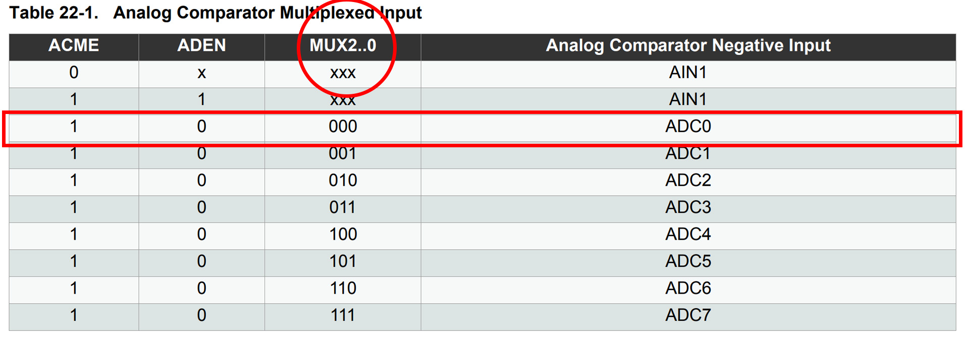
As you can see the table below, with ADEN set to 0 and ACME set to 1, by giving values to bits 2, 1 and 0 for the MUX value, we can select which of the inputs A0 to A7 will be connected to the negative input of the comparator. Let's say we want A0 to be connected. So we do ADMUX = 0. If you want A5 for example, it would be ADMUX = 5;
ADMUX = 0; // Select A0 as comparator negative input
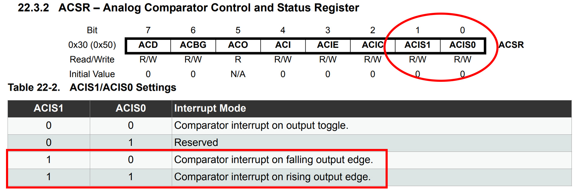
Remember from above that with bits ACIS0 and ACIS1 we select if the detection is made on rising edge or falling edge. These bits are bit 0 and 1 from the same ACSR register as before. So, as you can see below with "10" we set the mode on falling edge and with "11" we set it to rising edge. So, for example, we need to set bits ACSI 1 and 0 to be "1" and "1" so we do ACSR |= B00000011; in order to put bits 0 and 1 to be "1" and "1".
ACSR |= B00000011; // B00000011 - Set interrupt on rising edge*/
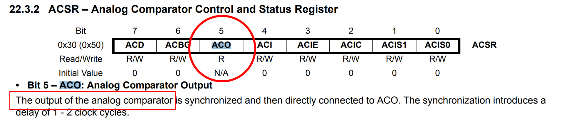
Ok, so now everything is set for the interruption rutine. Remember taht we have D6 as positive input, we have A0 as negative input and the comparator set to rising edge as you can see in the code below. Now let's take a look on how to use the interruption routine. So, the ACSR register bit 5 is the ACO bit. As you can see below, this bit has the value of the comparatour output. So just iamgine this, if we are into rising mode and ACO is "0", when ACO passes to be "1", that means the comaprator detected a pulse that rised above the signal palced on the positive input. So, each time ACO changes its value, the ISR will trigger.
  ACSR |= B00010000;      // Clear flag comparator interrupt (ACI bit to 1)
  ACSR &= B11011111;      // Set ACBG, to be equal to "0"
  ADCSRA = (0 << ADEN);   // Disable the ADC module because
  ADCSRB = (1 << ACME);   // Enable the MUX selector for negative input of comparator
  ADMUX = 0;              // Select A0 as comparator negative input
  ACSR |= B00000011;      // Set interrupt on rising edge*/
Remember that each time the comparator output changes from 1 to 0 or from 0 to 1, the ACO bit will also change and the ISR will trigger. So, the ISR (ANALOG_COMP_vect) loop will run. Now look at the code below. When we enter the interruption, first we check if we are into rising or falling mode by looking at the first 2 bits of the ACSR register, bits ACIS1 and ACIS0. If we are into falling mode and ACO is 0, taht means the signal changed from HIGH to LOW. If we are in to rising mode and ACO is 1, the signal changed from LOW to HIGH. To check the ACO value, we check bit 5 of the ACSR register with an AND (&) operation. Remember to change the mode for rising or falling for the next loop.
  // Interrumption vector for the Analog comparator
ISR (ANALOG_COMP_vect) {
  if(ACSR & B00000010)             //If we are into falling edge
  {
    if(!(ACSR & B00100000)) {      //If ACO is 0 (we have that ! for inverse)
      //A change from HIGH to LOW was detected
      //Do what you want to do here...
	  ACSR |= B00000011;      // Remember top set back the interrupt on rising edge for next ISR
    }
  }
  else                              //else, if we are into rising edge
  {
    if((ACSR & B00100000)){         //If ACO is 1
      //A change from LOW to HIGH was detected
      //Do what you want to do here...
	  ACSR |= B00000010;      // Remember top set back the interrupt on falling edge for next ISR
    }
  }
}
  void setup() {
  ACSR |= B00010000;      // Clear flag comparator interrupt (ACI bit to 1)
  ACSR &= B11011111;      // Set ACBG, to be equal to "0"
  ADCSRA = (0 && ADEN);   // Disable the ADC module because
  ADCSRB = (1 && ACME);   // Enable the MUX selector for negative input of comparator
  ADMUX = 0;              // Select A0 as comparator negative input
  ACSR |= B00000011;      // Set interrupt on rising edge*/
}

void loop() {
  //Do what you want to do in the loop...
}

// Interrumption vector for the Analog comparator
ISR (ANALOG_COMP_vect) {
  if(ACSR & B00100010)             //If we are into falling edge
  {
    if(!(ACSR & B00100000)) {      //If ACO is 0 (we have that ! for inverse)
      //A change from HIGH to LOW was detected
      //Do what you want to do here...
      ACSR |= B00000011;      // Remember top set back the interrupt on rising edge for next ISR
    }
  }
  else                              //else, if we are into rising edge
  {
    if((ACSR & B00100000)){         //If ACO is 1
      //A change from LOW to HIGH was detected
      //Do what you want to do here...
      ACSR |= B00000010;      // Remember top set back the interrupt on falling edge for next ISR
    }
  }
}
So guys, that's how you set and use the internal comparator. In my project of the Arduino ESC, I've used this comparator. Remember, the ESC has 3 phases so I needed inputs A0, A1 and A2 as negative input for the comparator. So, during the code; I've used the MUX bits to change between inputs and ACIS bits to change between rising and falling. Se the video below.
I hope that you like this tutorial. If you consider supporting my work, buy my PCBs on my shop, or maybe consider supporting me on PATREON or if you want, make a PayPal donation. Thank you very much.