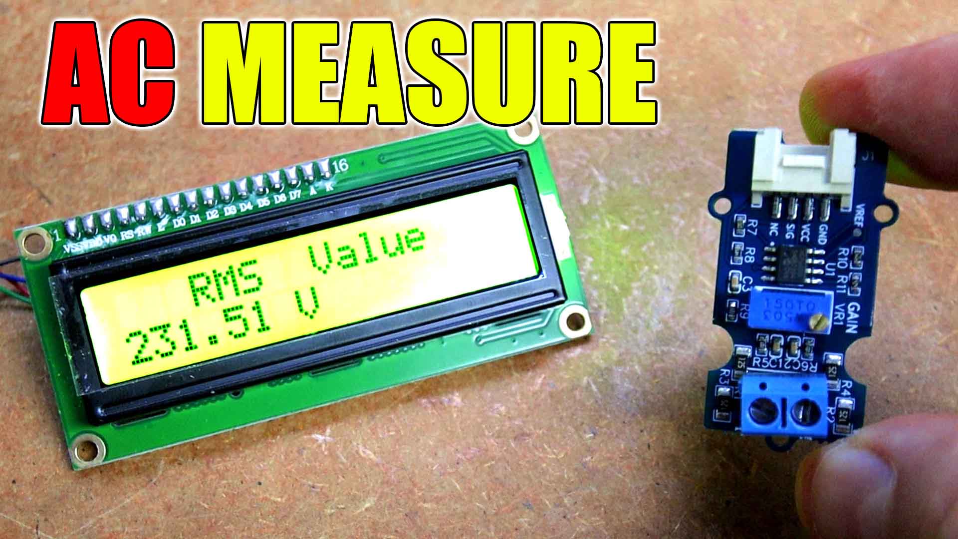
A few weeks ago, we’ve made this battery charger and protection circuit that was cutting the voltage when this was reaching 4.2V. To make that circuit I was using a ZENER diode, the TL431 but I never explain you this component works and what more it could do. This is actually a variable reference ZENER diode and it can be used in so many circuits. Today I will show you a few circuit examples that you can make with this component and you will see how useful it can be for so many applications. Fixed value current limiter, voltage reference or variable voltage reference, it can be used as a undervoltage or over voltage protection or as a delay timer and much more. So stay till the end of the video and learn everything about this component and see all the examples I have to show you. So, let’s get started.
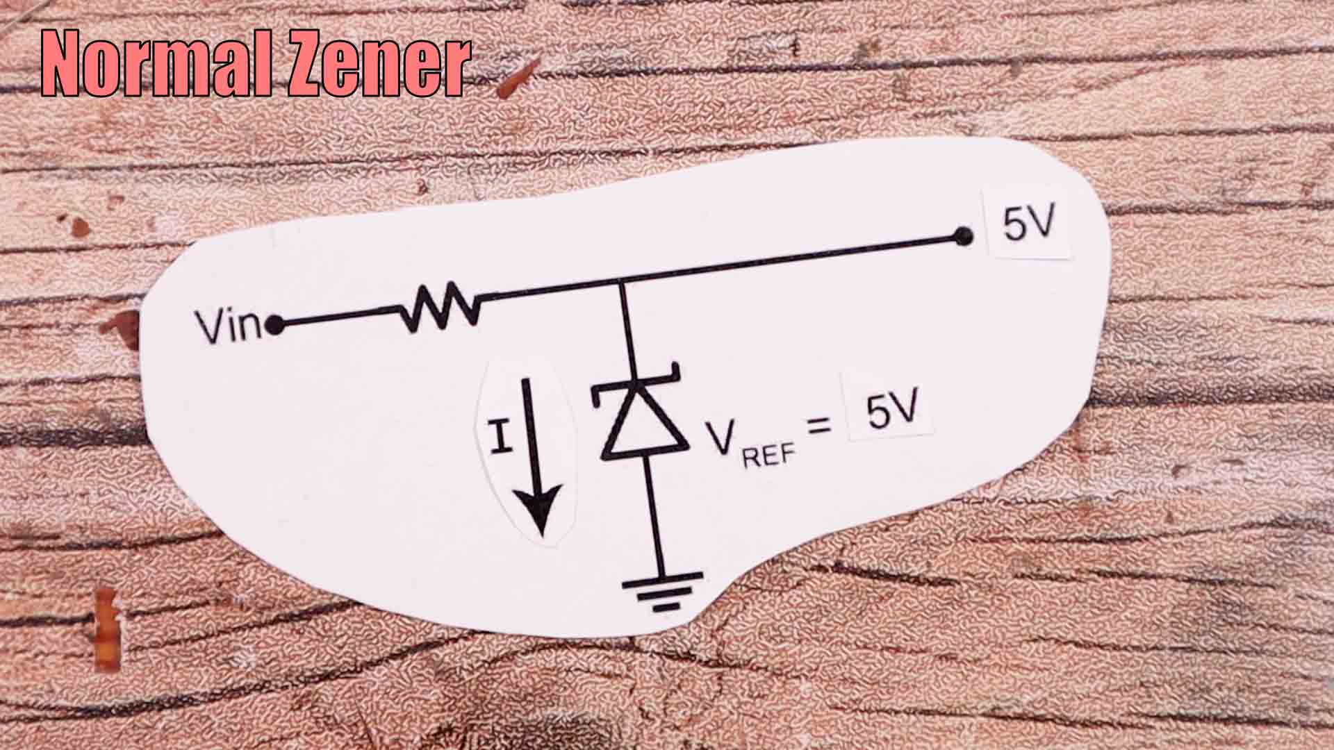
A normal ZENNER diode could be connected like below. The normal ZENNER diode usually has a voltage reference that we can find in the datasheet. If this reference voltage is for example 5V, what this component will do in the configuration below, is to allow the needed amount of current to pass towards ground, in such a way that the output will be regulated at 5V. But if you want a different voltage at the output, you need to change the diode by one that has that reference voltage. That’s why we use the TL431, because this one has a variable regulation voltage that can be changed on the third pin.
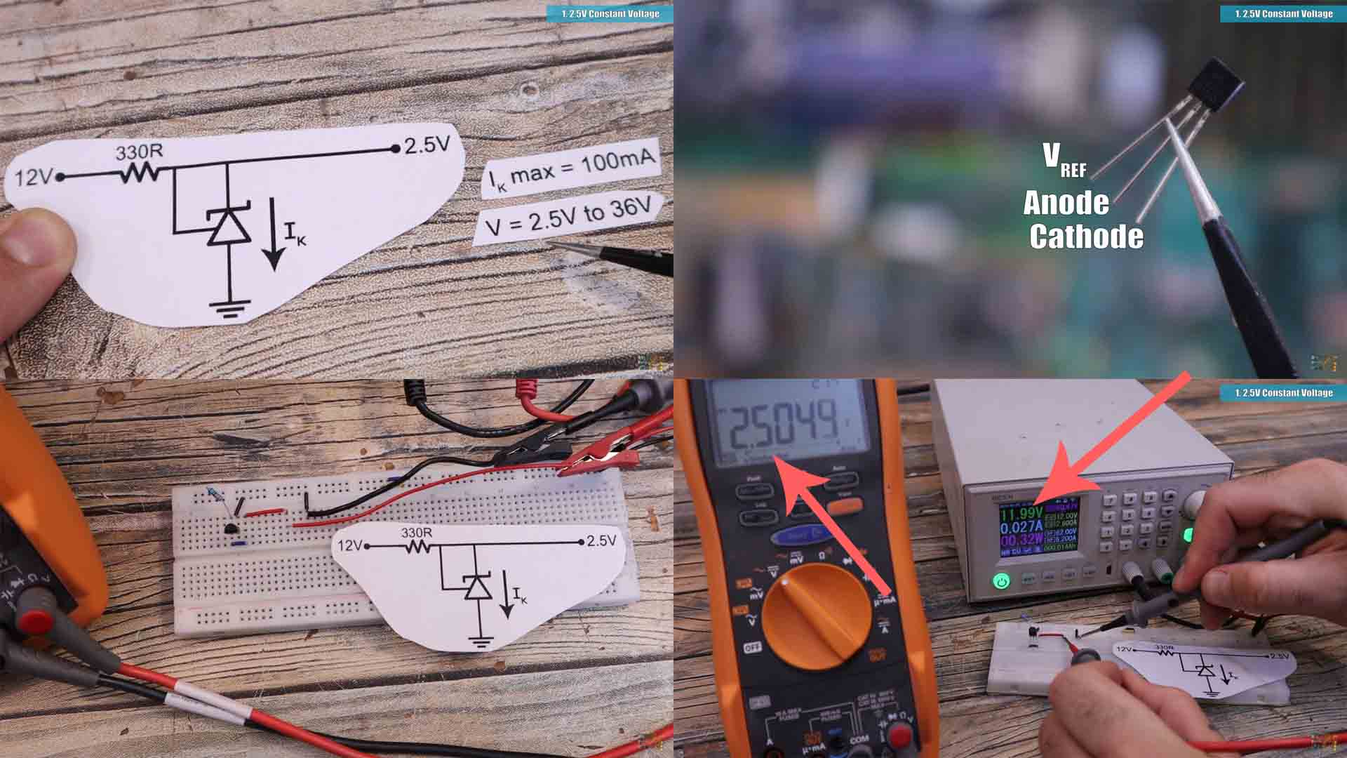
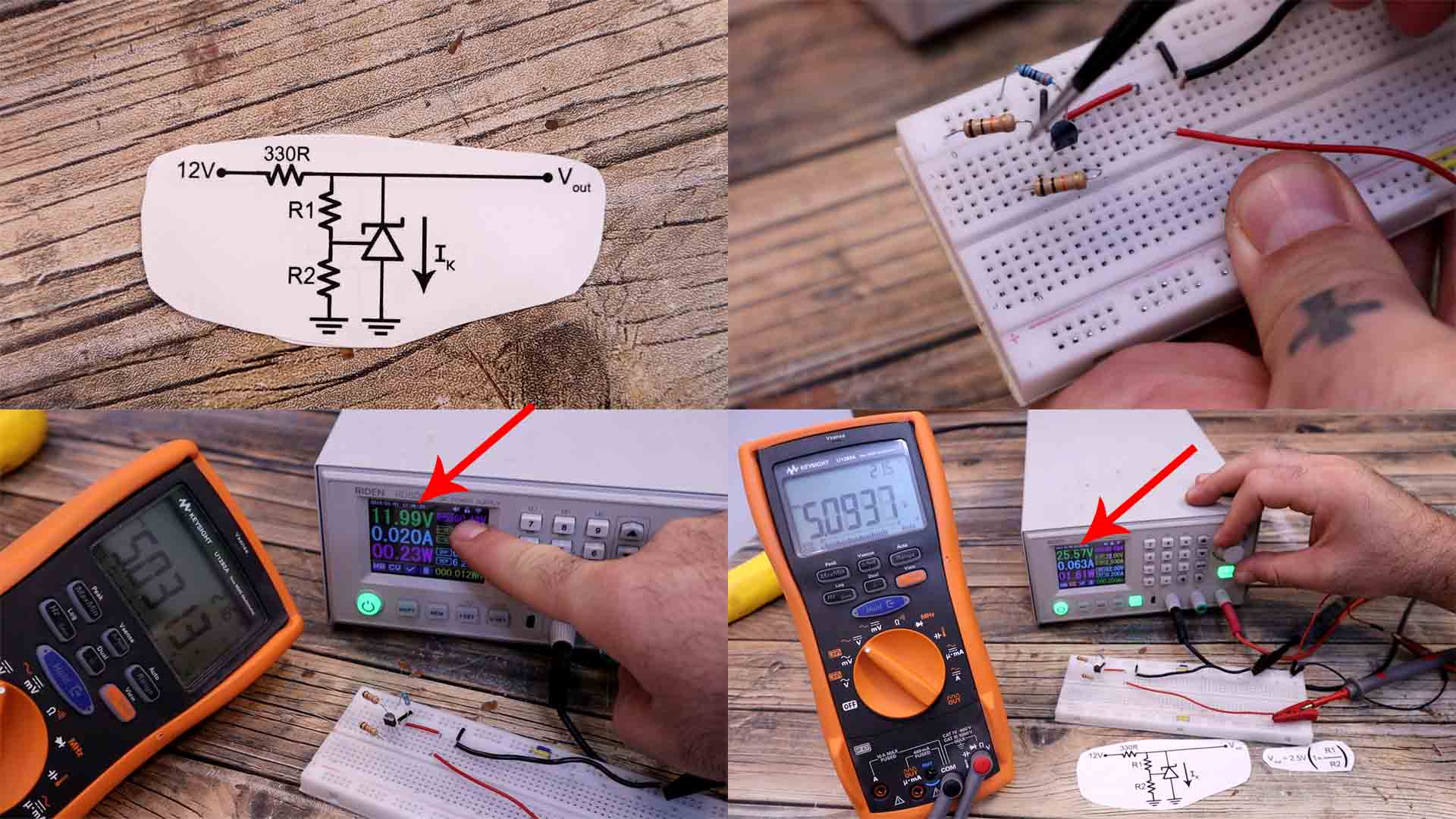
So let’s see the first circuit with this component. As you can see, contrary to a normal diode which has 2 pins, this one has 3 pins, anode, cathode and the reference voltage. So from the previous circuit we can make th one below. The problem is that the TL431 could consume a maximum of only 100mA, with more than that, it will burn out. And the voltage reference could be from 2.5V up to 36V. So with this circuit right now, since the reference is connected at the output, the value will be the minimum voltage of the TL431 which is 2.5V. To limit the current and not burn the IC I have a 330ohms resistor at the input. So, the current that passes through the IC is 29mA if the input is 12V. I have this circuit mounted on a breadboard and as you can see the input is 12V. But if I measure the output, it is stable at 2.5V.
But now, what if I want the output to be different that 2.5V. Let’s see the second example. Well, instead of connecting the reference pin at the output, we add a voltage divider. Now the output value would be equal to 2.5V multiplied by 1 plus the ratio between these two resistors. So for example if the resistors are both of 10K, the output would be 2.5 multiplied by 2, so it would be 5V. Changing the value of these resistors you can get any output from 2.5 up the 36V but have in mind the output can’t be higher than the input, obviously. I have this same circuit mounted on my breadboard. As you can see, this time the voltage output is 5V when the input is 12V. You could use this IC as a fixed value voltage refference for the Arduino analog read if you want. In case that you want a fixed value of 3V for example, you change the resistances and connect that output to the Aref pin of the Arduino. The good thing is that the 5V output won't change if the input changes, as you can see, I change the input to 25V and the output is still 5V.
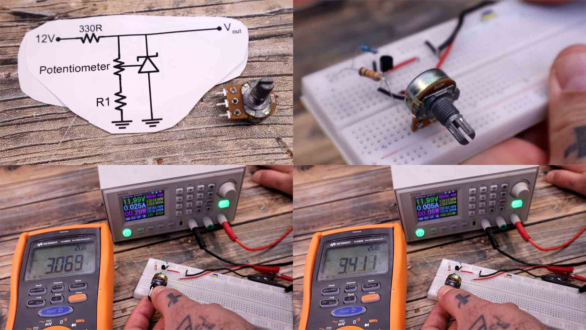
But now, for the third example, instead of adding fixed value resistors, let’s add a potentiometer. Now we can change the output value just by varying the potentiometer value. Here I have this simple circuit mounted on my breadboard. As you can see, using the potentiometer I can change the value at the output. This output is not affected by the input. As you can see, I change the input but the output is stable at the same value since the IC is making the regulation by consuming more or less current.
So as you can see you can use the TL431 as a voltage reference, also as a variable voltage output. I hope you like this tutorial and maybe you have learned something new. If my videos help you, consider supporting my work on my PATREON or a donation on my PayPal. Thanks again and see you later guys.