Solder allt the other components
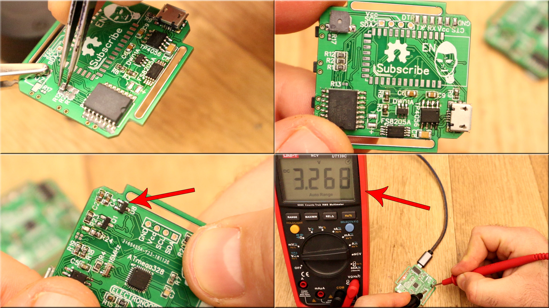
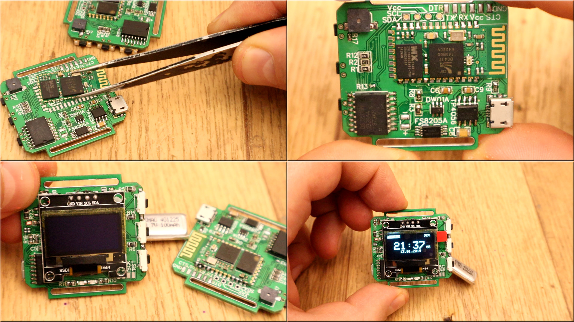
After you solder the Bluetooth module on the back, check once again all the voltages, connections, resistor and capacitor values and that everything works before you solder the OELD screen. Because once you solder the screen you can't see anything below. If everythin is ok, solder the OLED screen and the PCB is ready.
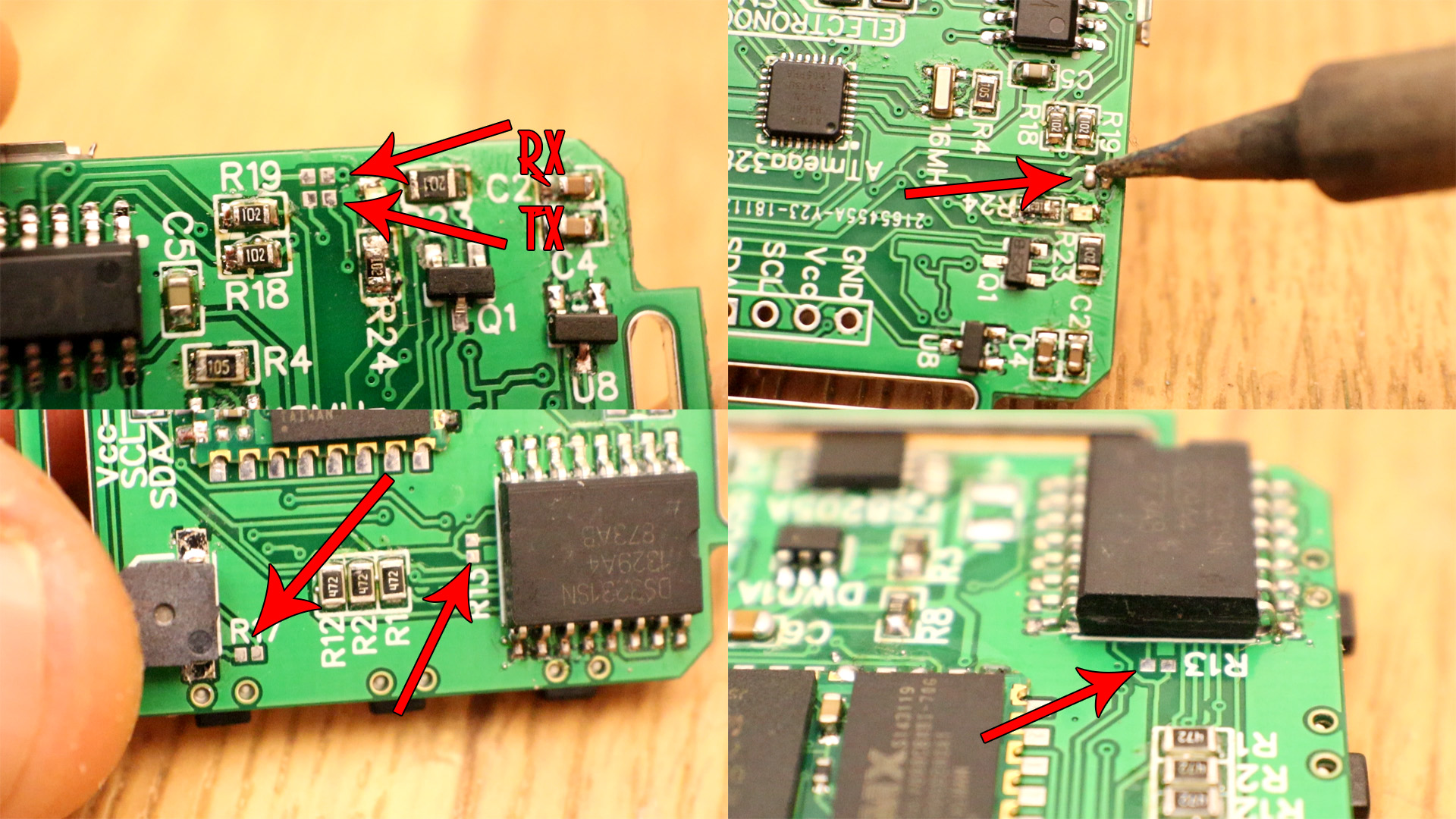
If you look on the PCB, as you can see below, we have a few pads. These are connections pads that are made with sodler. If the RX and TX pins are connected to the chip, we can't program it. So we haev to program the chip first, then make the connections on these pads using solder. If you want to re-uplaod another code, desolder the pads and uplaod the code and then make the connections back.
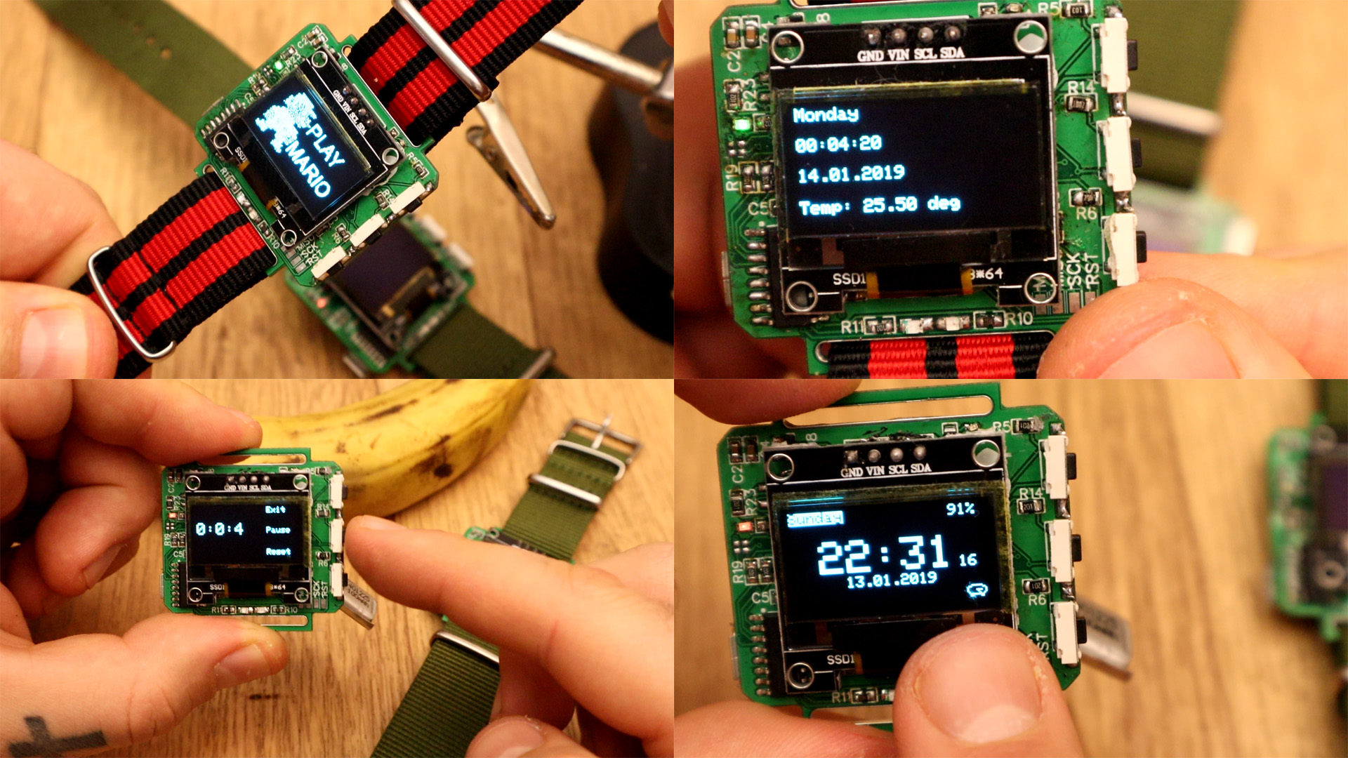
Now that we have the PCB ready, we can make all kind of programs with it. We can make it a watch, set alarms, play with LEDs, analog read tests, push buttons examples, OLED display logo print and a lot more. Also, if we make the connections on the Bluetooth pads, we can test the Bluetooth conenctions. See the enxt tutorials for an exampel of each part starting with the watch example.