You see, I’ve already made a few Arduino projects that used this NRF24 modules and I’ve already made a few Arduino based radio controllers. But you see, I never explained in detail how to make only the radio controller because it was always part of a bigger project such as the Arduino drone, or the 3D printed tank and also the Arduino radio controlled plane.
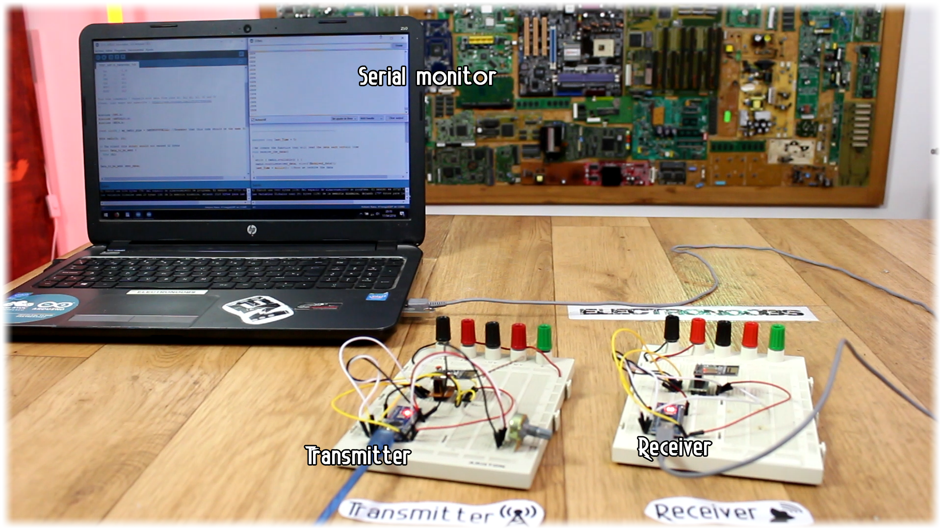
So, a lot of you guys had problems establishing the radio connection or understanding the code. So today I’ll make a tutorial on only how to create the radio controller and make it work just as a commercial controller. So, this project will have two parts, a transmitter and a receiver with outputs for each channel. I haven’t tested the range of this one, but with my past projects, which is more than the same, I had good signal up to 700 metres.
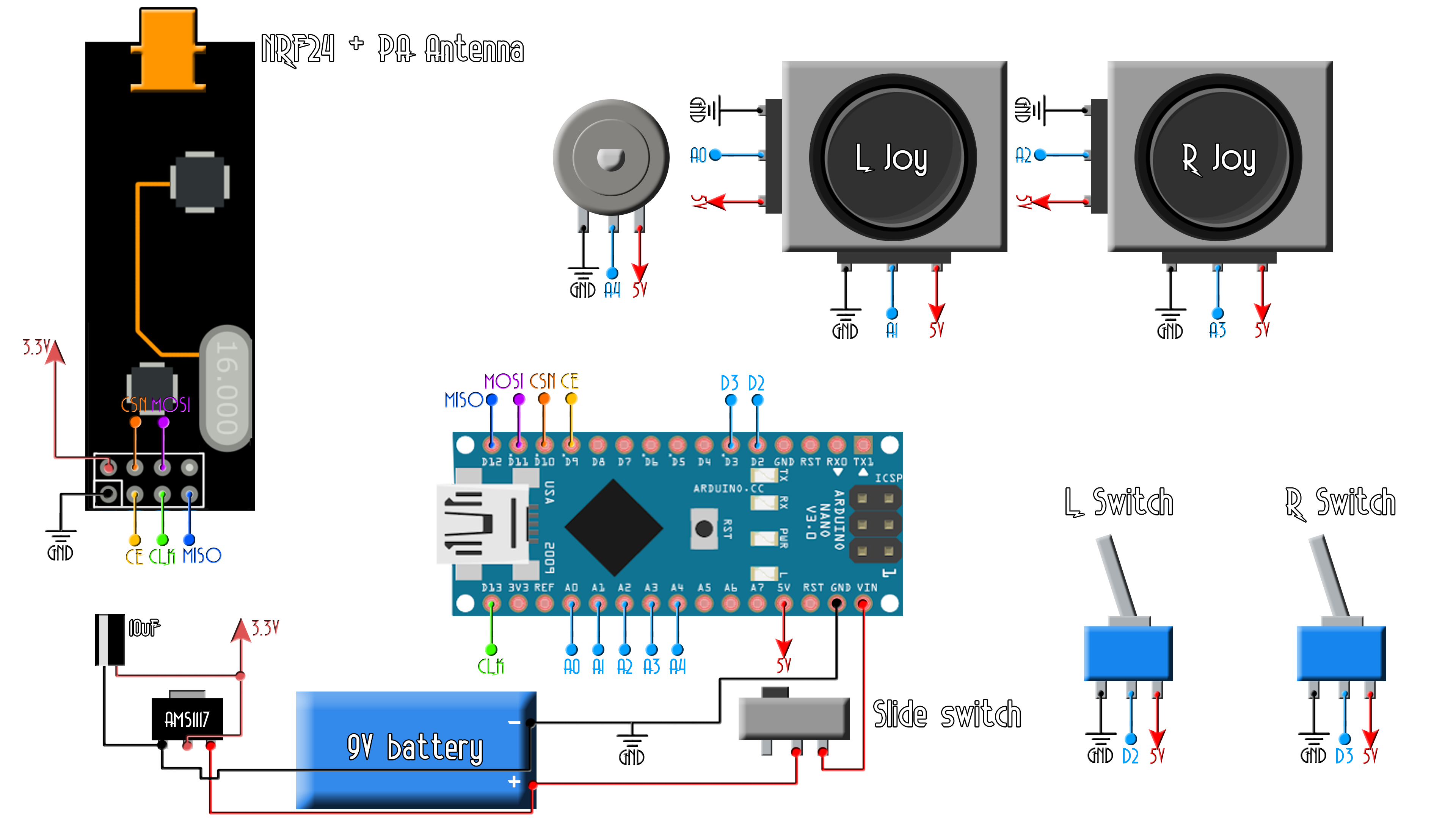
Before we build our radio controller, first let's test the radio connection between two NRF24 modules. On a breadboard connect the transmitter and the Arduino with only one potentiometer connected to analog pin A0. Use this example schematic for that. Make sure that the SPI connections it’s as in the schematic. You could also wind ground around the MOSI and MISO wires for less noise.
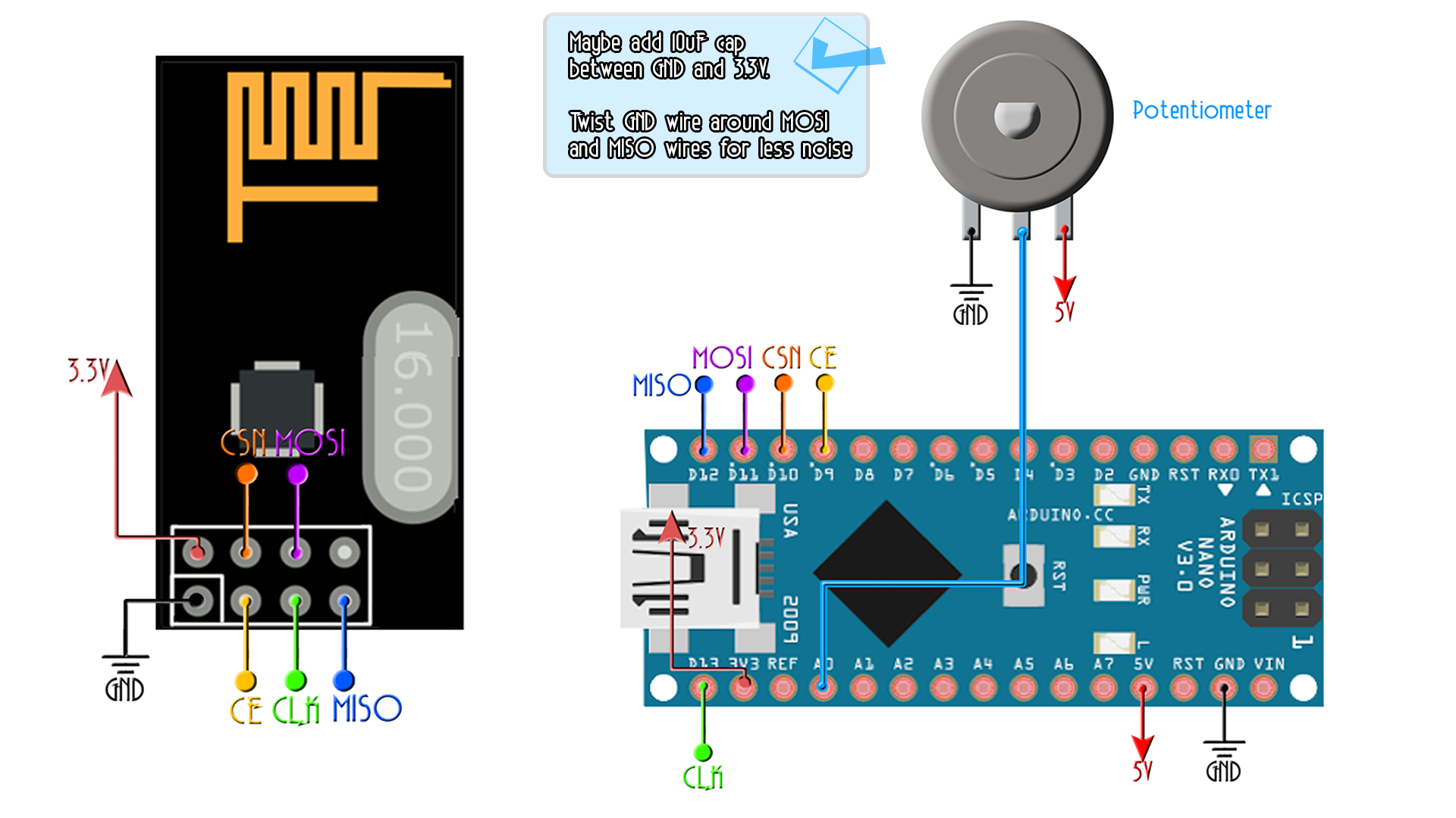
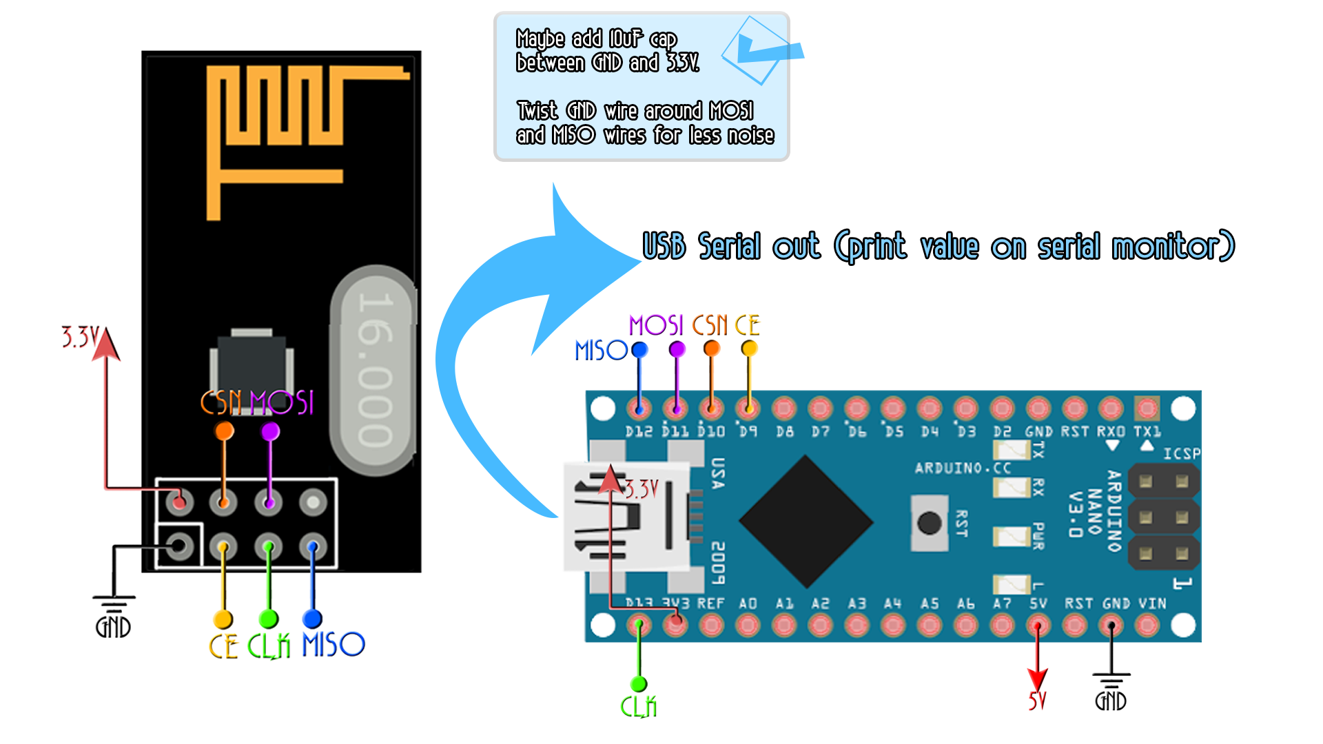
So this above will be the transmitter schematic that will send the data from the potentiometer. Now we do the same for the receiver but without the potentiometer. To print the received data we will use the serial monitor of the arduino with a baud rate of 9600. Now mount the next scheamtic for the receiver.
Ok, so now we have the transmitter with a Potentiometer connected to A0 on one breadboard and the receiver on the other. Let's upload some test code and see if we receive the data from the transmitter and print it on the serial monitor.
Now, download the next two codes. They are very simple. One reads the value of the potentiometer, creates a byte of data and send it. The other receives the data and print the value on the serial monitor. If you receive the data everything is ok. If you don't receive data, the value on the serial monitor is always the same, even if you rotate the potentiometer.
/* Tranmsitter code for the Arduino Radio control with PWM output
 * Install the NRF24 library to your IDE
 * Upload this code to the Arduino UNO, NANO, Pro mini (5V,16MHz)
 * Connect a NRF24 module to it:

    Module // Arduino UNO,NANO

    GND    ->   GND
    Vcc    ->   3.3V
    CE     ->   D9
    CSN    ->   D10
    CLK    ->   D13
    MOSI   ->   D11
    MISO   ->   D12

This code transmits 1 channels with data from pins A0 POTENTIOMETER
Please, like share and subscribe : https://www.youtube.com/c/ELECTRONOOBS
*/

#include <SPI.h>
#include <nRF24L01.h>
#include <RF24.h>

const uint64_t my_radio_pipe = 0xE8E8F0F0E1LL; //Remember that this code should be the same for the receiver

RF24 radio(9, 10);

// The sizeof this struct should not exceed 32 bytes
struct Data_to_be_sent {
  byte ch1;
};

Data_to_be_sent sent_data;


void setup()
{
  radio.begin();
  radio.setAutoAck(false);
  radio.setDataRate(RF24_250KBPS);
  radio.openWritingPipe(my_radio_pipe);
  sent_data.ch1 = 127;

}

/**************************************************/


void loop()
{
  /*If your channel is reversed, just swap 0 to 255 by 255 to 0 below
  EXAMPLE:
  Normal:    data.ch1 = map( analogRead(A0), 0, 1024, 0, 255);
  Reversed:  data.ch1 = map( analogRead(A0), 0, 1024, 255, 0);  */

  sent_data.ch1 = map( analogRead(A0), 0, 1024, 0, 255);

  radio.write(&sent_data, sizeof(Data_to_be_sent));
}
/* Receiver code for the Arduino Radio control with PWM output
 * Install the NRF24 library to your IDE
 * Upload this code to the Arduino UNO, NANO, Pro mini (5V,16MHz)
 * Connect a NRF24 module to it:

    Module // Arduino UNO,NANO

    GND    ->   GND
    Vcc    ->   3.3V
    CE     ->   D9
    CSN    ->   D10
    CLK    ->   D13
    MOSI   ->   D11
    MISO   ->   D12

This code receive 1 channels and prints the value on the serial monitor
Please, like share and subscribe : https://www.youtube.com/c/ELECTRONOOBS
*/


#include <SPI.h>
#include <nRF24L01.h>
#include <RF24.h>

const uint64_t pipeIn = 0xE8E8F0F0E1LL;     //Remember that this code is the same as in the transmitter
RF24 radio(9, 10);  //CSN and CE pins

// The sizeof this struct should not exceed 32 bytes
struct Received_data {
  byte ch1;
};

int ch1_value = 0;
Received_data received_data;


/**************************************************/

void setup()
{
  Serial.begin(9600);
  //We reset the received values
  received_data.ch1 = 127;

  //Once again, begin and radio configuration
  radio.begin();
  radio.setAutoAck(false);
  radio.setDataRate(RF24_250KBPS);
  radio.openReadingPipe(1,pipeIn);

  //We start the radio comunication
  radio.startListening();

}

/**************************************************/

unsigned long last_Time = 0;

//We create the function that will read the data each certain time
void receive_the_data()
{
  while ( radio.available() ) {
  radio.read(&received_data, sizeof(Received_data));
  last_Time = millis(); //Here we receive the data
}
}

/**************************************************/

void loop()
{
  //Receive the radio data
  receive_the_data();


  ch1_value = map(received_data.ch1,0,255,1000,2000);
  Serial.println(ch1_value);


}//Loop end
Ok, so upload the codes above, one to the transmitter and other to receiver. Make sure to open Arduino IDE two times so you could have two COM connected at same time. Go to receiver code and open serial monitor. It should have the value of the potentiometer printed with values from 1000 to 2000. If not, the connection isn't working.
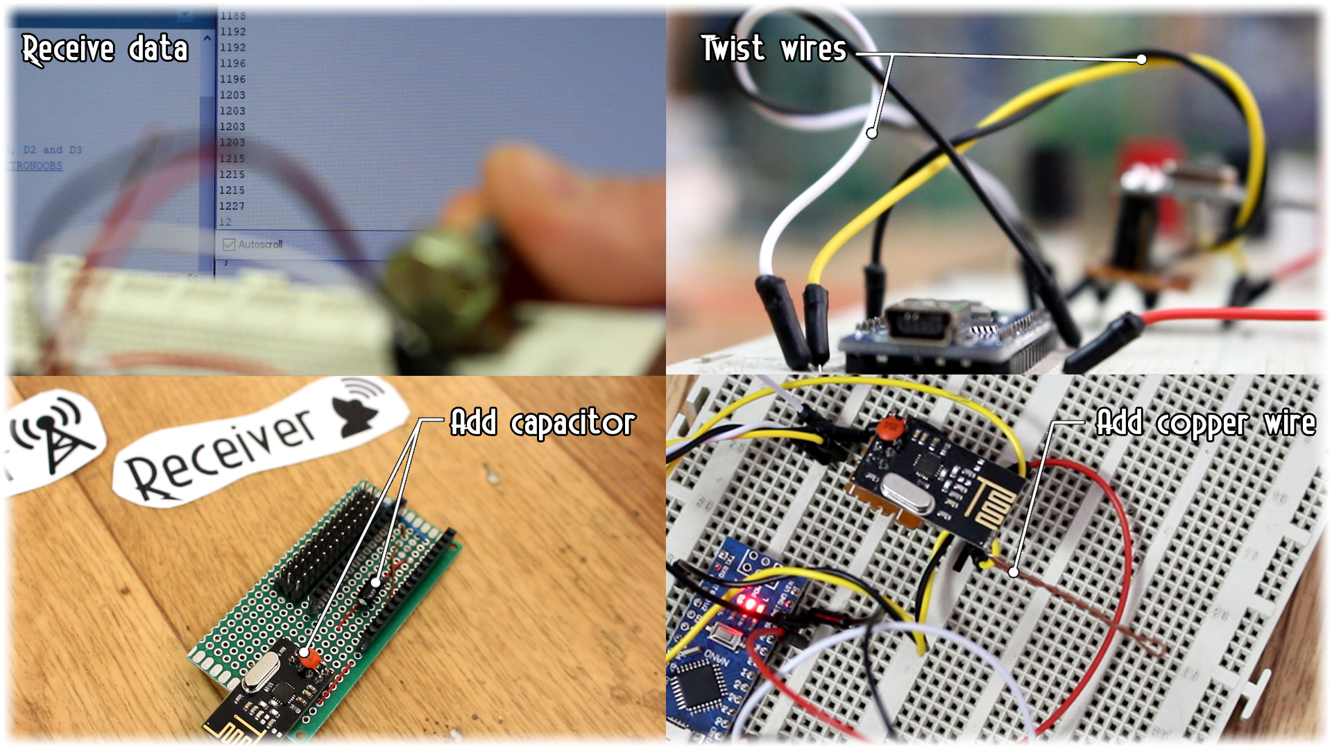
To improve connection you should do:
-Add 10uF capacitor to 3.3V.
-Wind GND around the SPI pins.
-Solder small copper wire to the PCB radio module
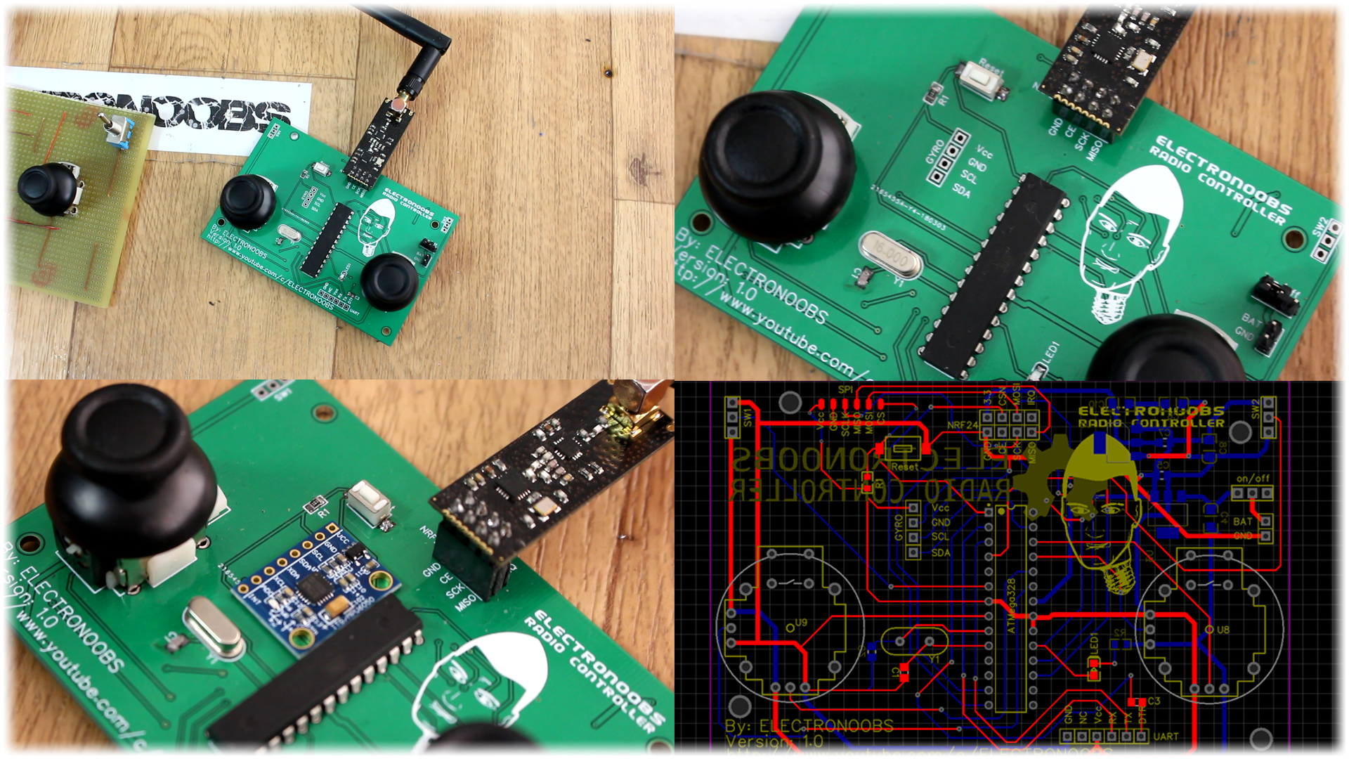
So, let’s start building this project. My transmitter will have 7 channels but it could have more if you want. I will have 4 analog channels for two joysticks. Then I'll use two toggle switches for 2 more digital channels and finally another analog channel for a potentiometer. On a drilled PCB I solder all the components as in the schematic below. For the transmitter you should use a power amplified one so we will have more range. You see, the transmitter needs a powerful radio module, but the receiver should work ok with a normal one as well. If the signal gets to it, it should work just fine.
I take the piece of drilled PCB and I first solder in place the joysticks. They have a thick metal pins, so you will probably have to enlarge 4 holes for each in order to be able to fit it in. Next, I solder the radio transmitter module in the top center position of the board so it won’t have too much interference. Now, a very important step is to solder the Arduino quite close to the radio module. You see, the longer are the wires or PCB connections from the Arduino to the module, the higher the noise will be. So, make sure you have very short connections.
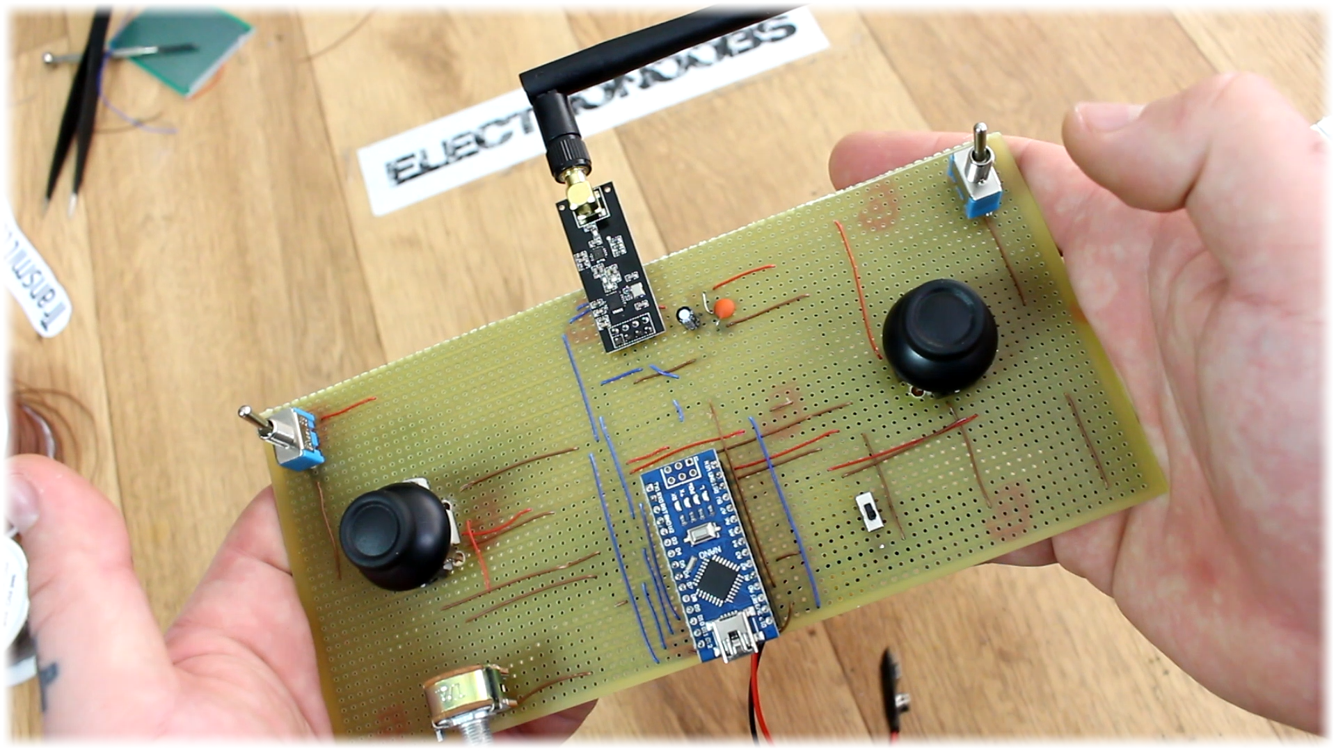
Next, I add the two toggle switches, one on each side and finally the extra potentiometer. To power on and off the board, I’ve added this kind of sliding switch. The battery will be connected to this switch so when we slide it on, the entire board will be supplied.
Finally, I solder the 3.3V voltage regulator with the coupling capacitors and make all the connections between, joysticks, radio module, Arduino and all the components, following the schematic. Now the board is ready. All is there to do is to program it.
If you want a better-looking board, feel free to download my design from below of this board. You have the GERBERS files in a zip below. Just download it and send it to JLCPCB and order your board for a very low price and give your project this professional look and also with a gyro control so you could move your radio control device just by moving the controller. Check the link below for more.