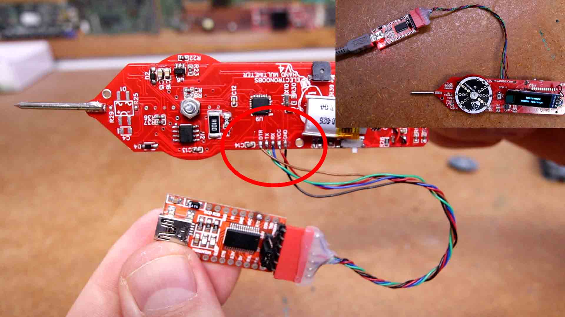
I connect this FTDI module to the UART pads and I open the code. Read it line by line to understand more but is still pretty much the same as for the previous versions. Detect the mode and inside each mode we use the formulas to measure each value. I recommend you to check my previous videos about the multimeter in order to understand how each block works. Compile and upload it to the multimeter. Now as you can see, by rotating the dial we can change between modes. Also, by pushing the button we change to the extra modes such as continuity, diode mode or frequency. When charging the red LED is turned on and when the battery is full, the blue LED will turn on.
/* Arduino Two Hand Multimeter V4.1 by ELECTRONOOBS (Voltage, resistance, capacitance, inductance, current, etc)
More info on: https://electronoobs.com/eng_arduino_tut194.php
Support on PATREON: https://www.patreon.com/ELECTRONOOBS
YouTube Channel: https://www.youtube.com/@ELECTRONOOBS
Video Here: https://youtu.be/lmUTQCBEtYU*/


/////////////////////////Library for INA219 CUrrent Module/////////////////////////////
#include <Wire.h>
#include <Adafruit_INA219.h>
Adafruit_INA219 ina219;
//////////////////////////////////////////////////////////////////////////////////////


/////////////////////////////Library for ADS1115 ADC//////////////////////////////////
#include <Adafruit_ADS1015.h>       //Download here: https://www.electronoobs.com/eng_arduino_Adafruit_ADS1015.php
Adafruit_ADS1115 ads(0x48);
//////////////////////////////////////////////////////////////////////////////////////

////////////////////////OLED 64x124 display with i2c//////////////////////////////////
//OLED screen libraries
#include <Adafruit_GFX.h>           //Download here: https://www.electronoobs.com/eng_arduino_Adafruit_GFX.php
#include <Adafruit_SSD1306.h>
#define OLED_RESET 11
Adafruit_SSD1306 display(OLED_RESET);
//////////////////////////////////////////////////////////////////////////////////////


//Define Inputs Outputs
int mode_selector = A3;           //My analog values were: 250, 800, 480, 336, 1024

//Voltage Mode
int VOLT_PIN_0 = 7;               //For voltage mode side of ADC0
int VOLT_PIN_1 = 12;              //For voltage mode side of ADC1

//Res Mode
int RES_PIN_2K = 8;               //Pin resistance mode for 2K divider
int RES_PIN_20K = 4;              //Pin resistance mode for 20K divider
int RES_PIN_470K = 5;             //Pin resistance mode for 470K divider

//Inductance Mode
int Induct_OUT = 6;               //Pin inductance mode to diode
int Induct_IN = 9;                //Pin inductance mode from OPAMP
int Induct_GND = A1;              //Pin inductance for GND simulate

//Cap Mode
int CapAnalogPin = A0;            //Pin for cap mode connected to Negative Probe
int CapAnalogPin2 = A2;           //Pin for cap mode connected to Positive Probe
int chargePin = 11;               //Pin for cap mode connected to 10K res
int dischargePin = 13;            //Pin for cap mode connected to 220R res

//BT module
int BT_MOS = A7;                  //Bluetooth module activation mosfer
int BT_RX = 2;                    //Bluetooth RX pin
int BT_TX = 3;                    //Bluetooth TX pin

//Extra
int Buzzer = A6;                  //Pin connected to an LED and buzzer
int Push_button = 10;             //Pin connected to the middle push button


/////////////////////Variables/////////////////////
int mode = 0;
int mode_prev = 0;
bool Push_button_state = true;
bool switch_once = false;

//Voltage mode
float VoltageReadOffset = 0.0;
float Voltage = 0.0;
float Volt_ref = 0;

//Resistance mode
float R2_1 = 2000;    //In ohms
float R2_2 = 20;    //In K ohms
float R2_3 = 470;     //in K ohms
int Res_Offset = 0;
int Continuity_Res_Offset = -2;
float D4_diode_ofset = 0.61;
bool conductivity = true;

//Capacitance mode
unsigned long startTime;
unsigned long elapsedTime;
float microFarads;
float nanoFarads;
#define resistorValue  10800.00F  //Remember, we've used a 10K resistor to charge the capacitor
bool cap_scale = false;
//Small scale
const float IN_STRAY_CAP_TO_GND = 56.88;
const float IN_CAP_TO_GND  = IN_STRAY_CAP_TO_GND;
const float R_PULLUP = 34.8;
const int MAX_ADC_VALUE = 1023;

//Inductance mode
double pulse, frequency, Induct_cap, inductance;

//Current mode
float Sensibility = 0.185;                      //Given by the ACS712 datasheet but tweeked a bit


//Frequency mode
unsigned long ontime;
unsigned long offtime;
unsigned long the_period;
float the_frequency;
float the_capacitance;


void setup() {
  Serial.begin(9600);
  pinMode(mode_selector, INPUT);
  pinMode(Push_button, INPUT_PULLUP);

  ads.setGain(GAIN_TWOTHIRDS);        //+/- 6.144V  1 bit = 0.1875mV (default)
  ads.begin();                        //Start the communication with the ADC

  if (!ina219.begin()) {
    Serial.println("Failed to find INA219 chip");
  }

  display.begin(SSD1306_SWITCHCAPVCC, 0x3C);  // initialize with the I2C addr 0x3C (for the 128x32 or 64 from eBay)
  delay(50);
  display.clearDisplay();             //Clean the buffer
  display.setRotation(2); //rotates text on OLED 1=90 degrees, 2=180 degrees
  display.setTextColor(WHITE);
  display.display();                  //Send data to screen

  delay(50);


  set_all_inputs();

  PCICR |= (1 << PCIE0);    //enable PCMSK0 scan
  PCMSK0 |= (1 << PCINT2);  //Set pin D10 trigger an interrupt on state change.
  mode_prev = mode;
}

void loop() {

  /////////////////////////////MODE SELECTOR/////////////////////////////////
  analogReference(DEFAULT);
  int mode_read = analogRead(mode_selector);
  //Serial.println(mode_read);

  if(mode_read > 190 && mode_read < 245){         //Voltage mode
    mode = 1;
  }

  else if(mode_read > 437 && mode_read < 720){    //Resistance mode
    if(mode != 7 && mode != 8){
      mode = 2;
    }
  }

  else if(mode_read > 317 && mode_read < 437){    //Inductance mode
    mode = 3;
  }

  else if(mode_read > 245 && mode_read < 317){    //Capacitance mode
    if(mode != 6){
      mode = 4;
    }
  }

  else if(mode_read > 720){                       //Current mode
    mode = 5;
  }

  else{
    Serial.println("No Mode");
  }

  if(mode != mode_prev){
    set_all_inputs();
    mode_prev = mode;
  }
  /////////////////////////////MODE SELECTOR/////////////////////////////////


  ////////////////////////////////MODE 1 VOLTAGE//////////////////////////////////
  if( mode == 1 ){
    pinMode(VOLT_PIN_1,OUTPUT);
    pinMode(VOLT_PIN_0,OUTPUT);
    digitalWrite(VOLT_PIN_1,LOW);
    digitalWrite(VOLT_PIN_0,LOW);
    float adc; // Leemos el ADC, con 16 bits
    adc = ads.readADC_Differential_0_1();

    Voltage = 11 * (adc * 0.1875)/1000 + VoltageReadOffset;
    /*I've used a 1K and 10K divider so outpout is 1/11 that's why we multiply voltage by  11*/

    //Serial.print(Voltage, 2);
    //Serial.println(" Volts");
    display.clearDisplay();
    display.setTextSize(1);
    display.setCursor(0,0);
    display.print("       VOLTAGE");    //Print text with line jump;

    display.setTextSize(2);
    display.setCursor(5,16);            //Move 16 pixels downwards and 5 to the right
    display.print(Voltage);
    display.print("V");
    display.display();

    delay(50);
  }
  ////////////////////////////////MODE 1 VOLTAGE//////////////////////////////////


  ////////////////////////////////MODE 2 RESISTANCE//////////////////////////////////
  if( mode == 2 ){
    pinMode(RES_PIN_20K,INPUT);
    pinMode(RES_PIN_470K,INPUT);
    pinMode(RES_PIN_2K,OUTPUT);
    digitalWrite(RES_PIN_2K,LOW);
    delay(100);

    float adc;
    float adc2;
    float res;

    adc = ads.readADC_SingleEnded(3);
    float vcc = 4.4 * (adc * 0.1875)/1000;
    vcc = vcc - D4_diode_ofset;
    adc2 = ads.readADC_SingleEnded(2);
    Voltage = (adc2 * 0.1875)/1000;
    res = ((R2_1*vcc)/Voltage) - R2_1 - Res_Offset;

    /*Serial.print("Vcc: ");
    Serial.println(vcc);
    Serial.print("ADC2: ");
    Serial.println(Voltage); */


    if(res < 0){
      display.clearDisplay();
      display.setTextSize(1);
      display.setTextColor(WHITE);
      display.setCursor(0,0);
      display.print("      RESISTANCE");    //Print text with line jump;
      display.setTextSize(1);
      display.setCursor(5,16);            //Move 16 pixels downwards and 5 to the right
      display.print("  INSERT RESISTOR");
      display.display();
    }

    else if(res > 0 && res < 2000){
      display.clearDisplay();
      display.setTextSize(1);
      display.setTextColor(WHITE);
      display.setCursor(0,0);
      display.print("      RESISTANCE");    //Print text with line jump;
      display.setTextSize(2);
      display.setCursor(5,16);            //Move 16 pixels downwards and 5 to the right
      display.print(res,0);
      display.print(" Ohms");
      display.display();
    }

    else if(res < 20000){
      pinMode(RES_PIN_2K,INPUT);
      pinMode(RES_PIN_20K,OUTPUT);
      pinMode(RES_PIN_470K,INPUT);
      digitalWrite(RES_PIN_20K,LOW);
      delay(100);

      adc = ads.readADC_SingleEnded(3);
      float vcc = 4.4 * (adc * 0.1875)/1000;
      vcc = vcc - D4_diode_ofset;

      adc2 = ads.readADC_SingleEnded(2);
      Voltage = (adc2 * 0.1875)/1000;
      res = ((R2_2*vcc)/Voltage) - R2_2;

      display.clearDisplay();
      display.setTextSize(1);
      display.setTextColor(WHITE);
      display.setCursor(0,0);
      display.print("      RESISTANCE");    //Print text with line jump;
      display.setTextSize(2);
      display.setCursor(5,16);            //Move 16 pixels downwards and 5 to the right
      display.print(res,1);
      display.print(" K");
      display.display();
    }
    else if(res > 20000){
      pinMode(RES_PIN_2K,INPUT);
      pinMode(RES_PIN_20K,INPUT);
      pinMode(RES_PIN_470K,OUTPUT);
      digitalWrite(RES_PIN_470K,LOW);
      delay(100);

      adc = ads.readADC_SingleEnded(3);
      float vcc = 4.4 * (adc * 0.1875)/1000;
      vcc = vcc - D4_diode_ofset;
      adc2 = ads.readADC_SingleEnded(2);
      Voltage = (adc2 * 0.1875)/1000;
      res = ((R2_3*vcc)/Voltage) - R2_3;

      if(res < 2000){
        display.clearDisplay();
        display.setTextSize(1);
        display.setTextColor(WHITE);
        display.setCursor(0,0);
        display.print("      RESISTANCE");    //Print text with line jump;
        display.setTextSize(2);
        display.setCursor(5,16);            //Move 16 pixels downwards and 5 to the right
        display.print(res,1);
        display.print(" K");
        display.display();
      }
      else{
        display.clearDisplay();
        display.setTextSize(1);
        display.setTextColor(WHITE);
        display.setCursor(0,0);
        display.print("      RESISTANCE");    //Print text with line jump;
        display.setTextSize(1);
        display.setCursor(5,16);            //Move 16 pixels downwards and 5 to the right
        display.print("  INSERT RESISTOR");
        display.display();
      }
    }
    delay(150);
  }//end mode 2
  ////////////////////////////////MODE 2 RESISTANCE//////////////////////////////////


  ///////////////////////////////MODE 3 Inductance //////////////////////////////////
  if( mode == 3){
    pinMode(Induct_GND, OUTPUT);
    digitalWrite(Induct_GND, LOW);


    display.clearDisplay();
    display.setTextSize(1);
    display.setTextColor(WHITE);
    display.setCursor(0,0);
    display.print("     INDUCTANCE");    //Print text with line jump
    display.display();

    pinMode(Induct_OUT, OUTPUT);
    pinMode(Induct_IN, INPUT);

    digitalWrite(Induct_OUT, HIGH);
    delay(5);                               //give some time to charge inductor.
    digitalWrite(Induct_OUT,LOW);
    delayMicroseconds(100);                 //make sure resination is measured
    pulse = pulseIn(Induct_IN,HIGH,5000);   //returns 0 if timeout
    if(pulse > 0.1)                         //if a timeout did not occur and it took a reading:
    {
      //#error insert your used capacitance value here. Currently using 2uF. Delete this line after that
      Induct_cap = 2.E-6;                                                   // - insert value here

      frequency = 1.E6/(2*pulse);
      inductance = 1./(Induct_cap*frequency*frequency*4.*3.14159*3.14159);  //one of my profs told me just do squares like this
      inductance *= 1E6;                                                    //note that this is the same as saying inductance = inductance*1E6

      display.setTextSize(2);
      display.setCursor(5,16);              //Move 16 pixels downwards and 5 to the right
      display.print(inductance,1);
      display.print(" uH");
      display.display();
      delay(100);
    }
    else{
      display.setTextSize(2);
      display.setCursor(5,16);              //Move 16 pixels downwards and 5 to the right
      display.print("None");
      display.display();
      delay(100);
    }
  }
  ///////////////////////////////MODE 3 Inductance //////////////////////////////////


  ///////////////////////////////MODE 4 CAPACITANCE//////////////////////////////////
  if( mode == 4){
    analogReference(DEFAULT);

    pinMode(CapAnalogPin,INPUT);
    pinMode(CapAnalogPin2, OUTPUT);
    pinMode(chargePin, OUTPUT);

    digitalWrite(CapAnalogPin2, LOW);
    digitalWrite(chargePin, HIGH);
    startTime = micros();

    while(analogRead(CapAnalogPin) < 645){

      }    //Get up to 63% of 1024

    elapsedTime= micros() - startTime;
    microFarads = ((float)elapsedTime / resistorValue);

    if (microFarads > 1)
    {
      display.clearDisplay();
      display.setTextSize(1);
      display.setTextColor(WHITE);
      display.setCursor(0,0);
      display.print("      CAPACITANCE");    //Print text with line jump;
      display.setTextSize(2);
      display.setCursor(5,16);              //Move 16 pixels downwards and 5 to the right
      display.print(microFarads,1);
      display.print(" uF");
      display.display();
      delay(100);
    }

    else
    {
      nanoFarads = microFarads * 1000.0;
      display.clearDisplay();
      display.setTextSize(1);
      display.setTextColor(WHITE);
      display.setCursor(0,0);
      display.print("      CAPACITANCE");    //Print text with line jump;
      display.setTextSize(2);
      display.setCursor(5,16);              //Move 16 pixels downwards and 5 to the right
      display.print(nanoFarads,1);
      display.print(" nF");
      display.display();
      delay(100);
    }

    digitalWrite(chargePin, LOW);
    pinMode(dischargePin, OUTPUT);
    digitalWrite(dischargePin, LOW);        //discharging the capacitor
    while(analogRead(CapAnalogPin) > 0){}   //This while waits till the capaccitor is discharged
    pinMode(dischargePin, INPUT);           //this sets the pin to high impedance
    //Serial.println("Discharging");

  }
  ///////////////////////////////MODE 4 CAPACITANCE//////////////////////////////////


  /////////////////////////////MODE 5 CURRENT/////////////////////////////////
  if( mode == 5)
  {
    float shuntvoltage = 0;
    float busvoltage = 0;
    float current_mA = 0;
    float loadvoltage = 0;
    float power_mW = 0;

    shuntvoltage = ina219.getShuntVoltage_mV();
    busvoltage = ina219.getBusVoltage_V();
    current_mA = ina219.getCurrent_mA();
    power_mW = ina219.getPower_mW();
    loadvoltage = busvoltage + (shuntvoltage / 1000);

    Serial.print("Bus Voltage:   "); Serial.print(busvoltage); Serial.println(" V");
    Serial.print("Shunt Voltage: "); Serial.print(shuntvoltage); Serial.println(" mV");
    Serial.print("Load Voltage:  "); Serial.print(loadvoltage); Serial.println(" V");
    Serial.print("Current:       "); Serial.print(current_mA); Serial.println(" mA");
    Serial.print("Power:         "); Serial.print(power_mW); Serial.println(" mW");
    Serial.println("");

    display.clearDisplay();
    display.setTextSize(1);
    display.setTextColor(WHITE);
    display.setCursor(0,0);
    display.print("       CURRENT");    //Print text with line jump;

    display.setTextSize(2);
    display.setTextColor(WHITE);
    display.setCursor(5,16);              //Move 16 pixels downwards and 5 to the right
    display.print(current_mA,0);
    display.println(" mA");
    display.display();
  }
  /////////////////////////////MODE 5 CURRENT/////////////////////////////////


  ////////////////////////////////MODE 6 FREQUENCY//////////////////////////////////
  if( mode == 6 ){
    noInterrupts();

    pinMode(CapAnalogPin2,INPUT);         //A2
    pinMode(CapAnalogPin,OUTPUT);         //A0
    digitalWrite(CapAnalogPin, LOW);      //A0

    ontime = pulseIn(CapAnalogPin2,HIGH); //A2
    offtime = pulseIn(CapAnalogPin2,LOW); //A2
    interrupts();

    the_period = ontime+offtime;
    the_frequency = 1000000.0/the_period;
    the_capacitance = 1 * (1.4427*1000000000)/(2545*the_frequency);   //calculating the Capacitance in nF
    display.clearDisplay();
    display.setTextSize(1);
    display.setTextColor(WHITE);
    display.setCursor(0,0);
    display.print("     FREQUENCY");    //Print text with line jump;
    display.setTextSize(2);
    display.setCursor(5,16);              //Move 16 pixels downwards and 5 to the right
    display.print(the_frequency,0);
    display.print(" Hz");
    display.display();
    delay(100);
  }
  ////////////////////////////////MODE 6 FREQUENCY/////////////////////////////////


  ///////////////////////////////MODE 7 CONTINUITY/////////////////////////////////
  if( mode == 7){
    pinMode(Buzzer, OUTPUT);
    pinMode(RES_PIN_20K,INPUT);
    pinMode(RES_PIN_470K,INPUT);
    pinMode(RES_PIN_2K,OUTPUT);
    digitalWrite(RES_PIN_2K,LOW);
    delay(100);

    float adc;
    float adc2;
    float res;

    adc = ads.readADC_SingleEnded(3);
    float vcc = 4.4 * (adc * 0.1875)/1000;
    vcc = vcc - D4_diode_ofset;
    adc2 = ads.readADC_SingleEnded(2);
    Voltage = (adc2 * 0.1875)/1000;
    res = ((R2_1*vcc)/Voltage) - R2_1 - Continuity_Res_Offset;

    /*Serial.print("Vcc: ");
    Serial.println(vcc);
    Serial.print("ADC2: ");
    Serial.println(Voltage);*/


    if(res < 1){
      tone(Buzzer, 3000, 1000);
      display.clearDisplay();
      display.setTextSize(1);
      display.setTextColor(WHITE);
      display.setCursor(0,0);
      display.print("     CONTINUITY");    //Print text with line jump;
      display.setTextSize(2);
      display.setCursor(5,16);             //Move 16 pixels downwards and 5 to the right
      display.print(res,1);
      display.print(" ohms");
      display.display();
    }
    else{
      digitalWrite(Buzzer, LOW);
      display.clearDisplay();
      display.setTextSize(1);
      display.setTextColor(WHITE);
      display.setCursor(0,0);
      display.print("     CONTINUITY");    //Print text with line jump;
      display.setTextSize(2);
      display.setCursor(5,16);             //Move 16 pixels downwards and 5 to the right
      display.print(" NONE");
      display.display();
    }


    delay(10);

  }
  ///////////////////////////////MODE 7 CONTINUITY/////////////////////////////////


  ////////////////////////////////MODE 8 DIODE//////////////////////////////////
  if( mode == 8 ){
    pinMode(RES_PIN_20K,OUTPUT);
    pinMode(RES_PIN_470K,OUTPUT);
    pinMode(RES_PIN_2K,OUTPUT);
    digitalWrite(RES_PIN_2K,LOW);
    digitalWrite(RES_PIN_470K,LOW);
    digitalWrite(RES_PIN_20K,LOW);
    delay(100);

    float adc;
    float adc2;
    float res;

    adc = ads.readADC_SingleEnded(3);
    float vcc = 4.4 * (adc * 0.1875)/1000;
    vcc = vcc - D4_diode_ofset;
    adc2 = ads.readADC_SingleEnded(2);
    Voltage = (adc2 * 0.1875)/1000;
    //res = ((R2_1*vcc)/Voltage) - R2_1 - Res_Offset;
    float diode_Voltage = (vcc - Voltage) - 0.02;
    /*Serial.print("Vcc: ");
    Serial.println(vcc,3);
    Serial.print("ADC2: ");
    Serial.println(Voltage,3);*/

    display.clearDisplay();
    display.setTextSize(1);
    display.setTextColor(WHITE);
    display.setCursor(0,0);
    display.print("       DIODE");    //Print text with line jump;

    if(Voltage > 0.05){
      display.setTextSize(2);
      display.setCursor(5,16);            //Move 16 pixels downwards and 5 to the right
      display.print(diode_Voltage,2);
      display.print(" V");
      display.display();
    }

    else {
      display.setTextSize(2);
      display.setCursor(5,16);            //Move 16 pixels downwards and 5 to the right
      display.print(Voltage,2);
      display.print(" V");
      display.display();
    }


    delay(150);
  }//end mode 2
  ////////////////////////////////MODE 8 DIODE//////////////////////////////////


}//END of void loop


void set_all_inputs(){
  pinMode(CapAnalogPin,INPUT);              //A0
  pinMode(Induct_GND, INPUT);               //A1
  pinMode(CapAnalogPin2,INPUT);             //A2
  pinMode(mode_selector, INPUT);            //A3
  //A4 is for SDA                           //A4
  //A5 is for SCL                           //A5
  pinMode(Buzzer, INPUT);                   //A6
  pinMode(BT_MOS,INPUT);                    //A7
  pinMode(BT_RX,INPUT);                     //D2
  pinMode(BT_TX,INPUT);                     //D3
  pinMode(RES_PIN_20K,INPUT);               //D4
  pinMode(RES_PIN_470K,INPUT);              //D5
  pinMode(Induct_OUT,INPUT);                //D6
  pinMode(VOLT_PIN_0,INPUT);                //D7
  pinMode(RES_PIN_2K,INPUT);                //D8
  pinMode(Induct_IN,INPUT);                 //D9
  //D10 is push button (already input)      //D10
  pinMode(chargePin,INPUT);                 //D11
  pinMode(VOLT_PIN_1,INPUT);                //D12
  pinMode(dischargePin,INPUT);              //D13
}


ISR(PCINT0_vect){
  if(!digitalRead(Push_button)){
    if(mode == 4){
      mode = 6;
      delay(100);
    }

    else if(mode == 6){
      mode = 4;
      delay(100);
    }

    if(mode == 2){            //If resistance mode
      mode = 7;               //Switch to continuity mode
      delay(100);
    }

    else if(mode == 7){       //If continuity mode
      mode = 8;               //Then resistance mode
      delay(100);
    }

    else if(mode == 8){       //If continuity mode
      mode = 2;               //Then resistance mode
      delay(100);
    }
  }
}