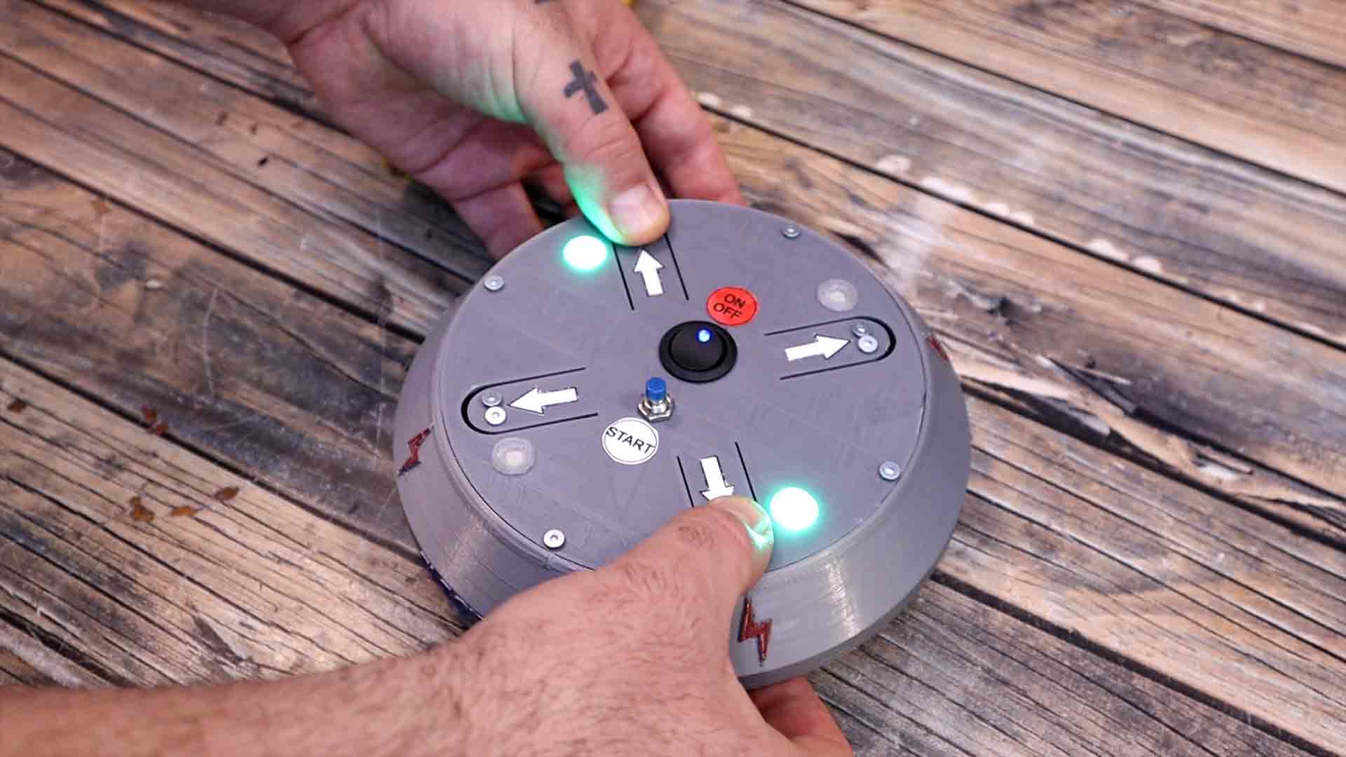
Today we have a "shocking project" and is not just a figure of speach. This is called a shocking game and obviously, this is a homemade version. Don’t worry this is working with very low power so is quite difficult to hurt you but it will give you a small zap in your finger. Anyway, I have to say this: please be careful since this is working with high voltage so make sure you don’t increase the power. For this game you have 4 pads that the players must push with their finger. If you remove your finger the game will pause till all the players have their finger on the buttons. And by the way, with the middle push button you can select the amount of players. Then you push the middle button and it will start rotating the lights and plying a suspense sound. Using a random timer, it will select one of the players and zap him with a short pulse of high voltage. You get zapped, you lose the game, and that’s pretty much how you play this. You can select from 2 up to 4 players. Before we start guys, please consider giving me a like or comment on my video. It will only take you a second but otherwise my channel will stay forever with this low amount of views. Anyway, let me show you how this works and how to make one, so let’s get started.
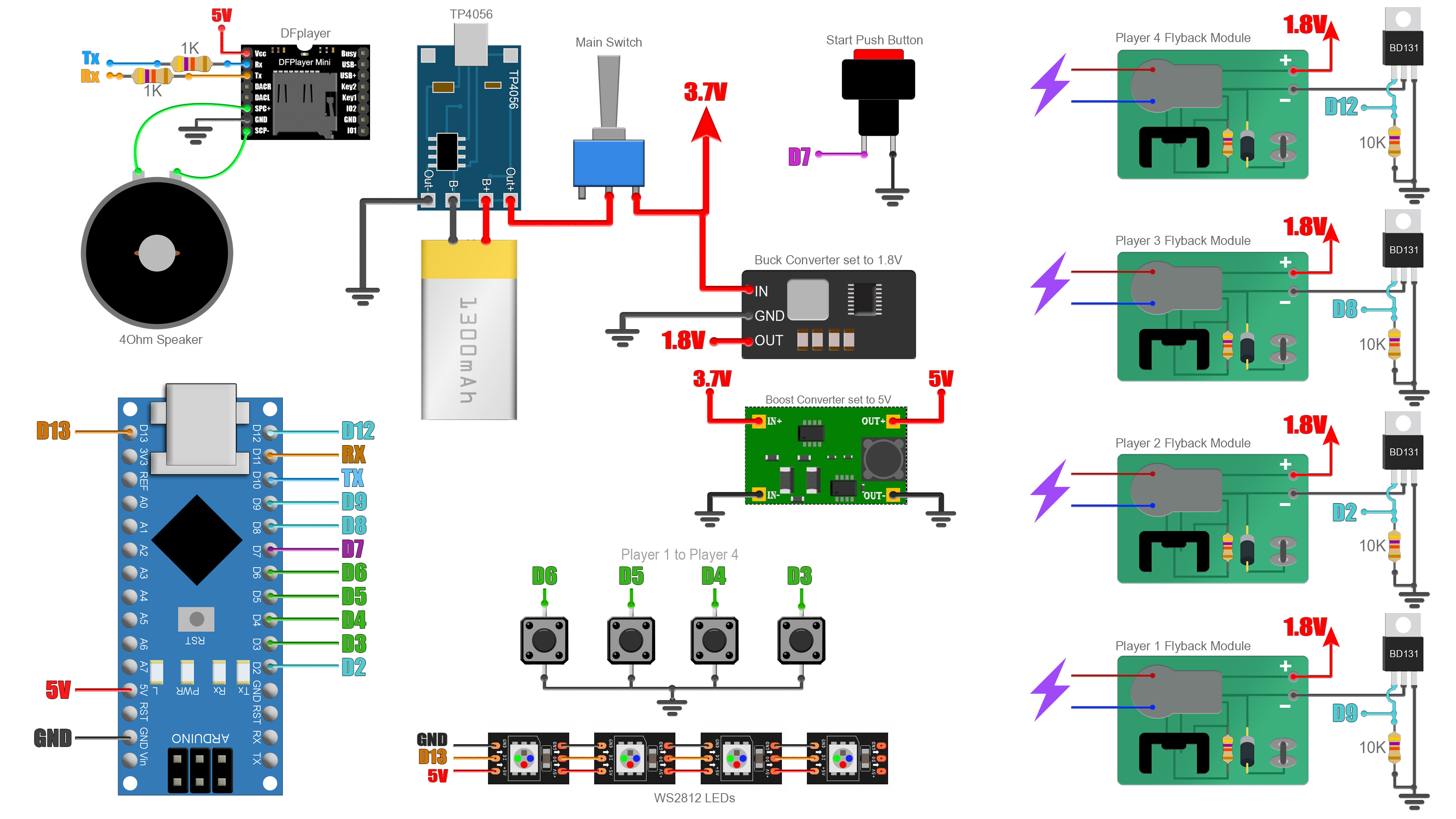
To create the high voltage "zaps", we need to use high voltage flyback transformers (low power one). This has a thick wire on one side with just a few loops and very thin wire on the secondary with a lot of loops. That will give us a huge ratio so we can increase the voltage a lot. I will supply each transformer using a transistor, in that way I can select which one to activate and for how long. Obviously, I will control the transistors with an Arduino. We also need a DF player and a speaker, a micro SD, an on and off switch, a push button, some addressable LED so we can use RGB colors, a 3.7V battery and a USB charging module. We also need a boost converter and a buck converter and you will see why in a moment.
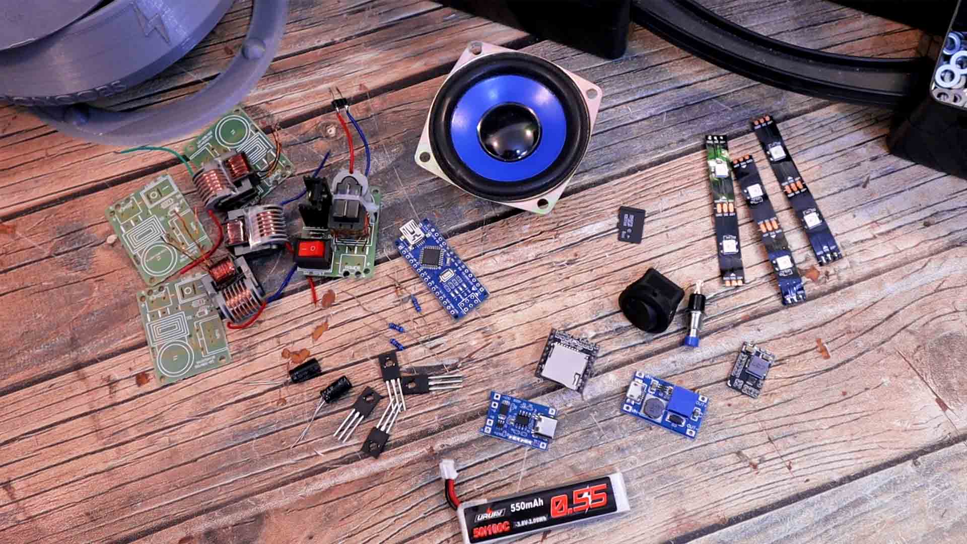
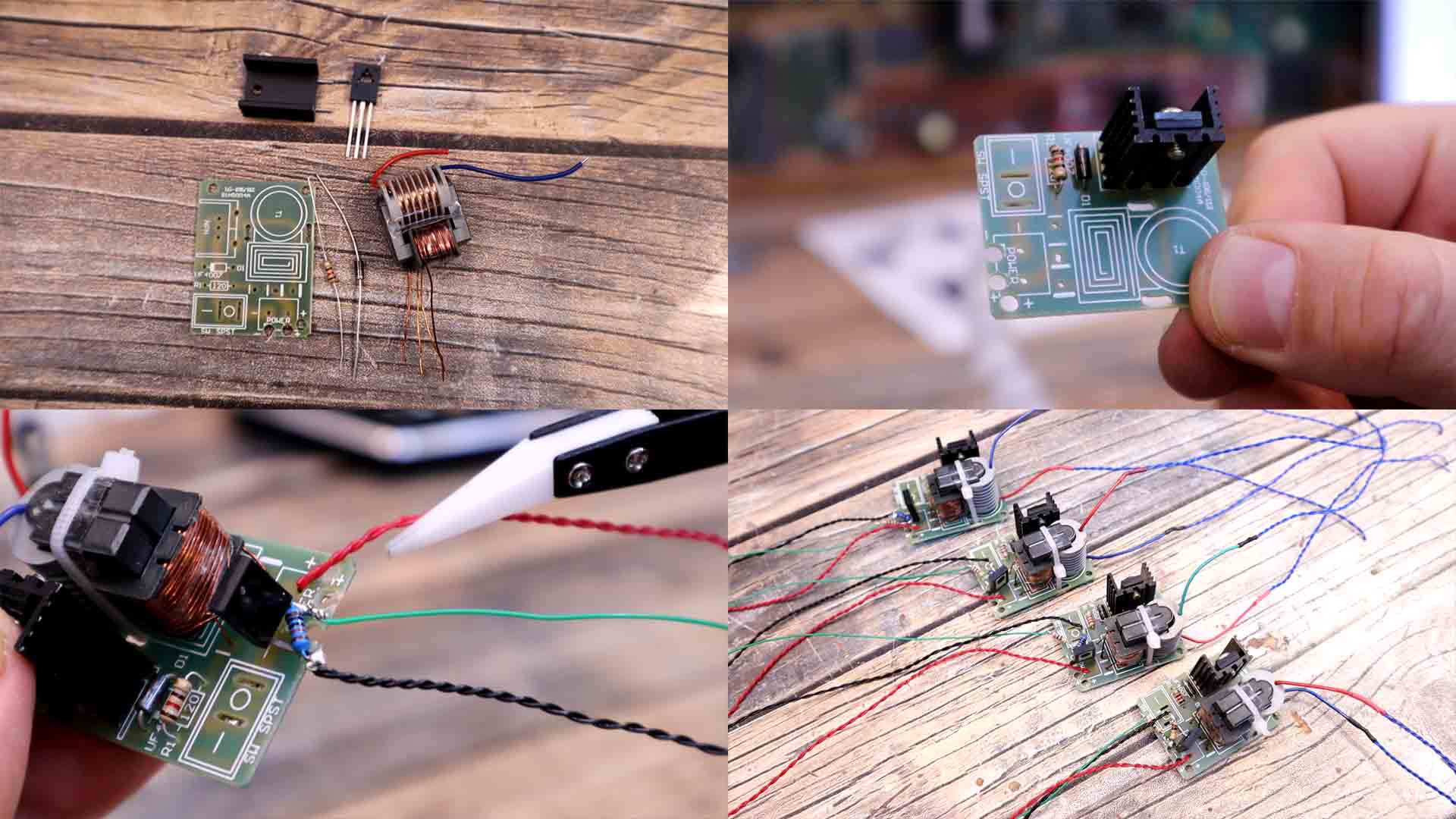
You can buy these flyback transformers as a kit for just a few dollars and they already give you a PCB and some basic components in order to create high frequency oscillation. You could also find this kind of transformers, like this one here, in any LCD monitor or TV, because they use high voltage for the backlight. And for the circuit, if you want to make it yourself, is just a small oscillator made between the flyback coli, a BJT transistor, a diode and a resistor, nothing fancy.
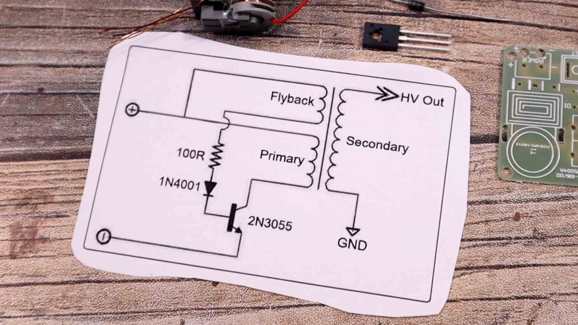
That was pretty much all we need to make the project so go below and see schematic and have it in front of you. We have each HV module with a NPN at the input so we can turn them on and off with a digital pin from the Arduino. Use the buck converter to get 5V and supply the Arduino, the DFplayer and the RGB LEDs. Use the buck converter to get 1.8V and supply the HV modules.
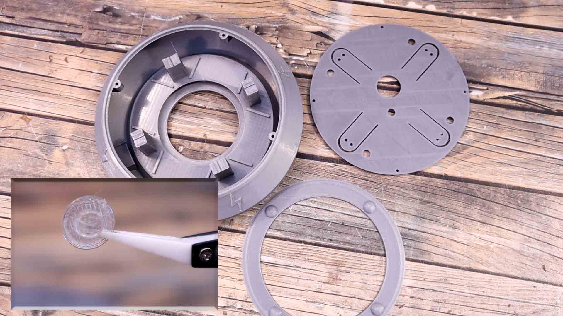
I’ve used PLA material, 0.2mm layer height and a 0.4mm nozzle using 2 perimeters and 20% infill. For the main base I had to use supports up to the layer 20 so make sure you activate that otherwise the speaker hole part will be printed in mid-air. We have 3 parts. The main case which has all sort of spaces inside for the electronics, the top plate where the buttons will go and some feet, so the case will have clearance from the ground. We will also use these translucid 3D printed buttons. I’ve used a grey color filament but you could always spray paint the parts with whatever color you want.
The first step is to solder all the high voltage modules. That’s very easy since we only have 4 components. Add the diode, the resistor and this BJT transistor together with the heat dissipator. Then we add the transformer and as you can see on the PCB, we have to solder a thin wire, then a thin wire together with a thick one and finally just a thick wire. Don’t solder the button switch to the PCB because instead of that, we will add a transistor. Solder these pads together so the transformer is always ON. Then we add a transistor to the input with a pulldown to ground and a wire connected to the gate. So now the flyback transformer module should have 3 wires. One is for 1.8V from the buck converter, one is ground and the third one is for the signal applied to the gate and with that we turn on and off the module. Make the same for all 4 modules.
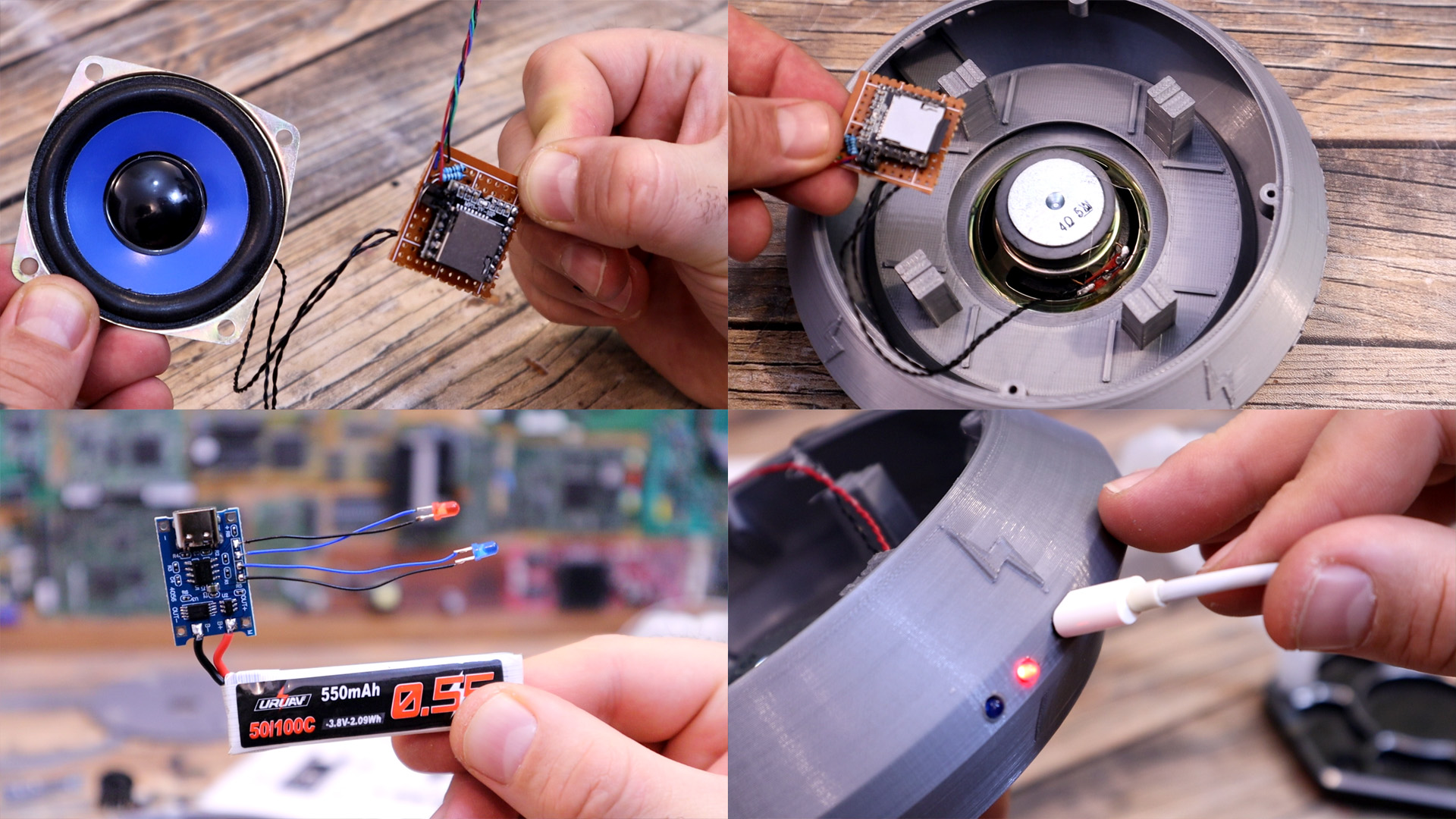
Now we make the rest of the connections. Solder wires to the speaker and then connect it to the DFPLAYER on a small prototyping PCB. I also add wires for 5V, ground and the TX and RC connections. Now we can glue the speaker on the bottom side of the main case. Make sure you get the SD card and download the mp3 files from the description. Copy the mp3 folder to this empty micro-SD card. Insert the card into the DFPLAYER.
Now I get the battery and solder it to the battery charger and protection module. This module will cut off power when the battery is low and also charge the battery. I also de-solder the charging LEDs from the PCB and in place of those I solder two trough-hole LEDs of 3mm. I now glue the charger module inside the case where I’ve prepared a place just in front of a hole. We use this hole to connect the USB charger. I add those two LEDs inside the holes so we can see then the battery is charging from the outside. I also find a place for the battery make sure I have long enough wires for positive and negative. Positive from the battery will go later to the main switch and from there we supply the rest.
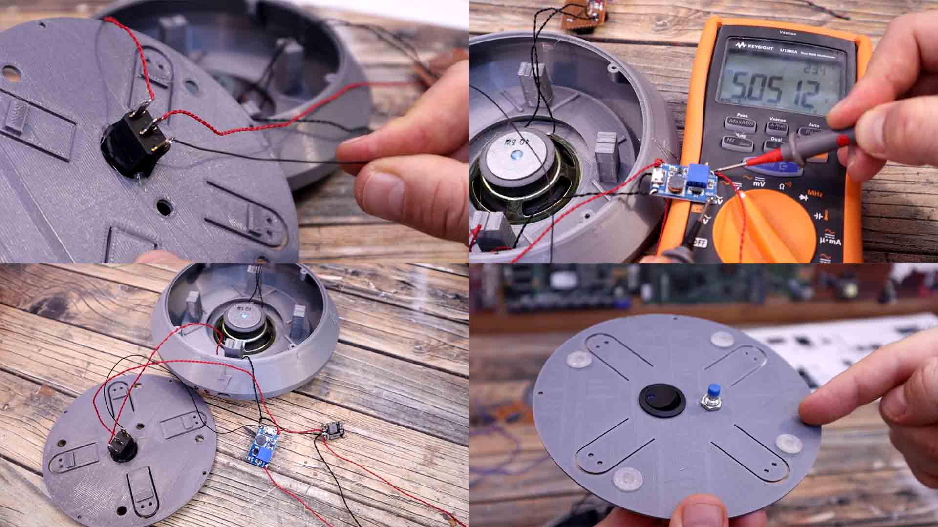
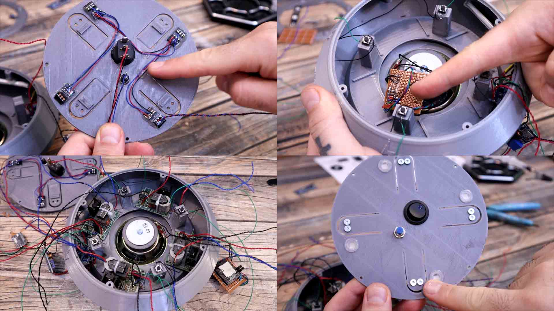
On the top plate I add the switch. I solder the positive wire from the battery here and another red wire that will go to the circuit. I also add a thin ground wire that is used for the internal LED that this kind of switch has integrated. Like that we know when the switch is ON. I solder the boost converter to the supply wires. I connect the multimeter at the output and make sure that the output is around 5V. To the same wires from the switch, I solder the buck converter. But first make sure you solder the 1.8V connection on the back. This will supply the transformers. On this top plate I also add the push button we will use to start the game. Then I add the translucid 3D printed parts on these 4 holes. Now, I cut 4 addressable LEDs from the WS12 28 strip. I glue the LEDs just in front of the hole on the bottom side. Like that the light will glow inside the translucid 3D printed part. I solder wires to the button and the LEDs and have them prepared for the final connections.
Finally, I get 4 small push buttons. I solder wires to each, a black one and a green one. Once I have the wires, I use some hot glue and fix them in place on the plastic pillars inside the main case. Like that, when I add the top part, the plastic will push the buttons and we can check if the player is touching the pad or not. Finally, I get the high voltage modules that I’ve prepared before. I glue each one of them inside the case. Then, on the plastic pads on the top case I add some screws. The wires from the transformers will go connected to these screws and like that we make connection with the finger of the player. Everything is in place and we have a lot of wires.
All is there to do is to solder these wires to the Arduino as in the schematic. It took me a while but now everything is connected. I've placed the Arduino with some glue on a wood board and solder all the wires. Now Download from the next aprt the Arduino code and the needed libraries for the DFPLAYER and the LED strip. Remember to also download the mp3 sounds and uplaod that folder to the SD card. Compile the code and upload it to the Arduino. Please read the code line by line because I always comment the steps so you could fully understand the routine. Now that the code is up, we can close the case. Make sure all wires are well connected and you could also give the game a test and if it works. We use screws to close the case. First, I will add some insertion threads. Using my soldering iron, I push one thread inside each hole. Now we can add screws. I close the case and this project is done and it also looks quite awesome, right? I also glue the feet part below with some super glue. Now the case has some clearance from the ground so the sounds from the speaker can get out.
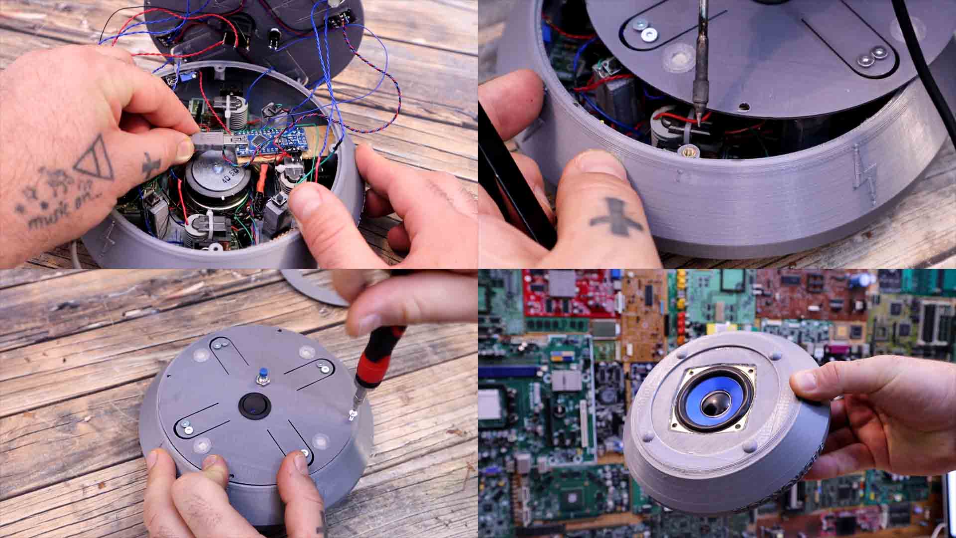
I've also printed some labels on paper and I will glue them on the case. One for the start button and the ON OFF switch and some arrows for each player. I've also painted these electric flashes with red color. And then the ELECTRONOOBS logo with blue and the game is finished. Get the code, the libraries and the mp3 files from below. See a full tutorial on how to use the DFPlayer here. Extract the mp3.zip file from below. Copy the mp3 folder to an empty SD card with fromat FAT32. Make sure you copy the entire folder not just the mp3 files. On the SD card there must be a folde rcalled mp3 and inside it we have the sounds marked as 0000.mp3, 0001.mp3, etc.
Let me explain you how it works step by step so we turn it on. If you short-press the start button you can select the amount of players from 2 to 4. Let’s select 2 players for the first example. Now if you long press the button for a few seconds, the game will start. But if not all the players are pushing the button the game will stay in pause mode and the LEDs are fading in an out and we can hear a mystical sound. Now if I press any 2 buttons, the game will start. As you can see, you can use any pair of buttons, the game will automatically detect where each player will go. Wait for a moment and a random player will get zapped. In the code I’ve used a real random timer so the victim will be selected at random. When time is up, you get zapped with a short pulse, and that’s it. The electric pulse is made between those two metal screws touching your finger.
I could stay more over the code and make more modes, but I think is enough for now and fun to play with your friends. Kind of a Russian Roulette but with electronics. If my videos help you, consider supporting my work on my PATREON or a donation on my PayPal. Thanks again and see you later guys.