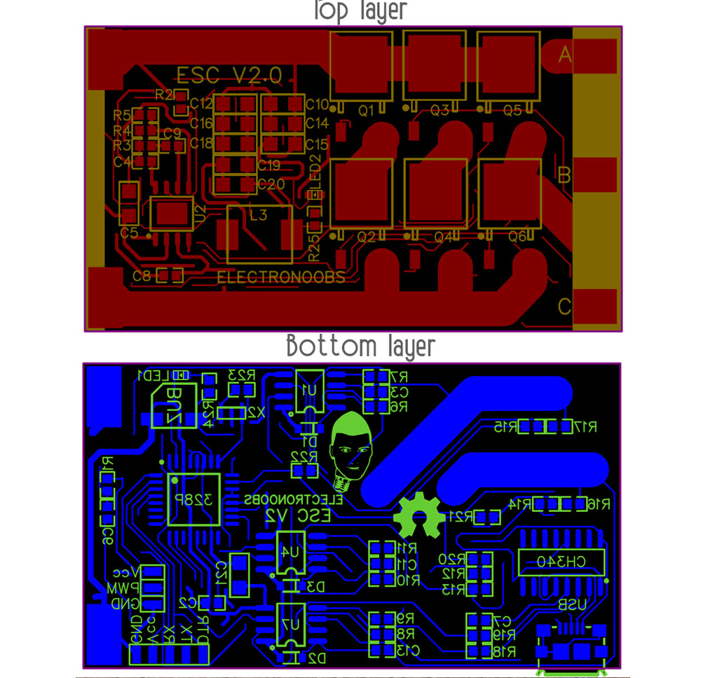
Here we have the top and bottom layout of this board. By the way, you could see the full tutorial and make your own board like this one,
here on this link. We can see on the top layer the 5V regulation buck converter circuit with the coil and the IC. Then on the right side we have the power MOSFETs and the triple phase output. Also, from the left side to the MOSFETs we have thick tracks and these tracks will have to withstand huge currents.
On the bottom side we have the ATmega328 microcontroller, the MOSFET drivers, the PWM input, a buzzer, LEDs and more... We also have the CH340 IC with a USB connector for UART programming of the microcontroller. Maybe this part is a bit overkill since we don't program the chip too often.