I've been trying to make a good ESC for years. My first prototype 3 years ago was working "good". It was very big and the BEMF was not that good. It could reach decent speeds and you ahve that tutorial here on this page. Now, with my final version I have all taht I wanted. High speed, good BEMF detection and that means good torque, PWM control of the speed and small size. The board is programed in Arduino.
So what is an ESC? Well, electronic speed controllers are used to control brushless motors, in thisc ase the motor has a triple phase input. To control this input, the ESC must apply a special sequence of LOWs and HIGHs signals in a predefined order. It has to conmutate very fast and by taht rotate the rotor of the motor. In this tutorial we will see how to control the rotation, the speed, detect the BEMF and by that know when to make the switch to the next step of the sequence. So this is a sensorless brushless motor speed controller since it uses no sensor to detect the rotor position. We will learn:
- The schematic and why we need each part
- Triple phase MOSFET bridge control
- BEMF detection and 0 cross
- Interrumprions and internal comparator of ATMEGA328
- PWM control
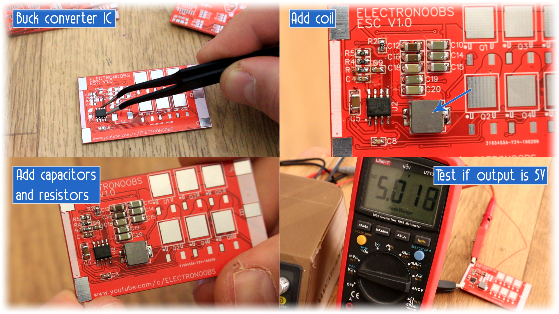
Now the schematic might look complicated but is not. First things first, we have a power block. This is a buck converter circuit that will give 5V for all the digital parts. The main input could be from 11 to 18V but this block will aloways give 5V. The next block is the triple phase bridge. These are 6 MOSFETs in a bridge configurations that are used to energise the coils of the motor. Each of these MOSFETs has a driver control with the IR2101 which is a dual driver so it could control both the high and low sides of the bridge.
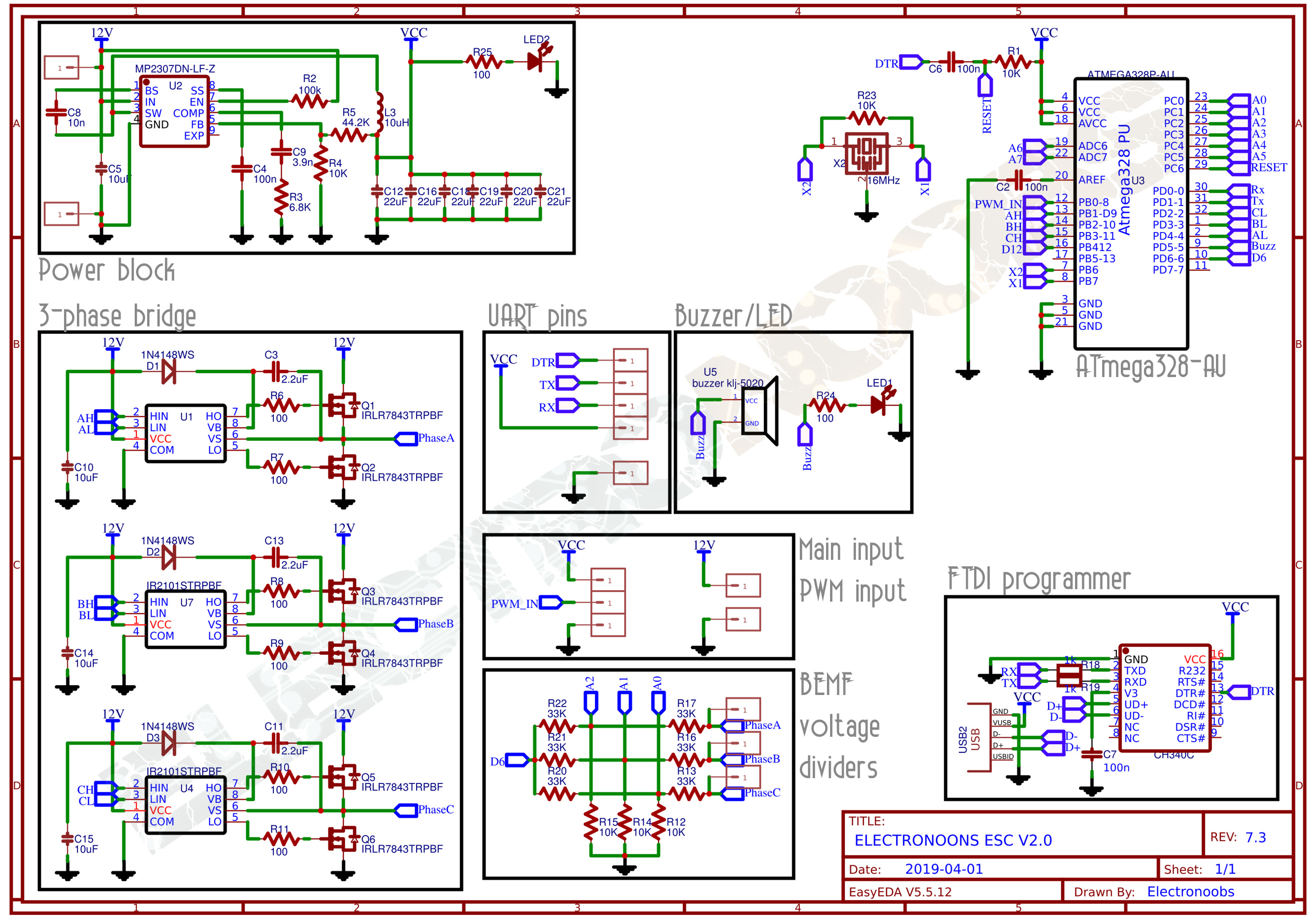
We have the BEMF voltage dividers block. The voltage from the motor will be higher than the maximum voltage that the ATmega328 could tahe as input, in this case 5V. So for that, using some resistors of 10K and 33K we lower the voltage so the analog input of the ATmega328 could read that. This inputs will be used to detect the position of the rotor and know when to switch to next step of the rotating sequence. We also have the ATmega328 microcontroller, the CH340 programmer so we could upload codes with the USB connector and a few more extra components such as buzzer, LEDs and pads.
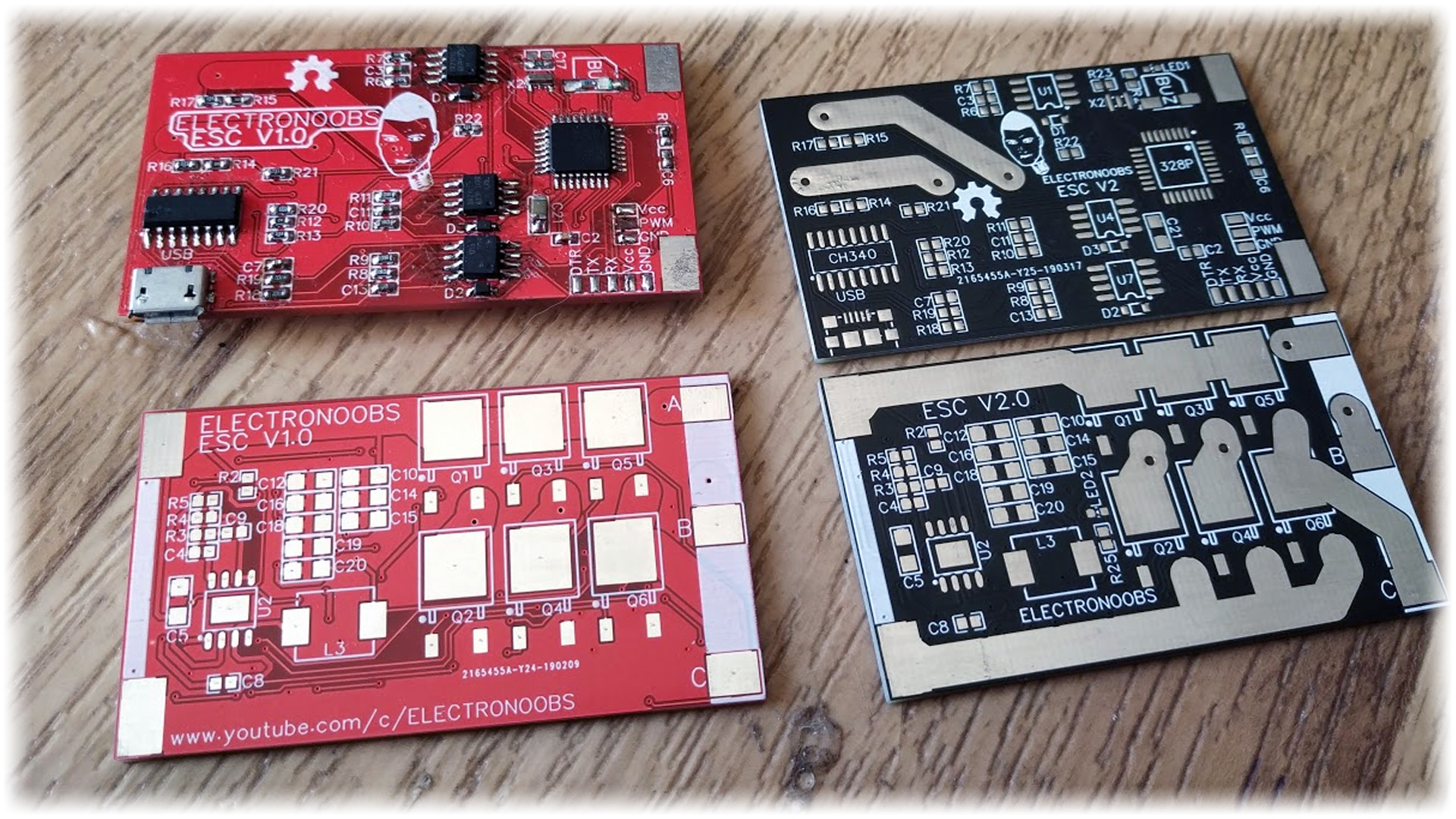
The PCB I've designed is 60 by 35 mm. In the photo below you can see the first version of the PCB in red but also the final version with black soldermask. The V1.0 had some errors such as some bad GND connections, wrong pin for the Buzzer and also the power tracks were covered by the soldermask. For version V2.0 now all the problems are fixed and the big tracks are exposed so I could fill those with solder for more current. You can download the gerber files from below.
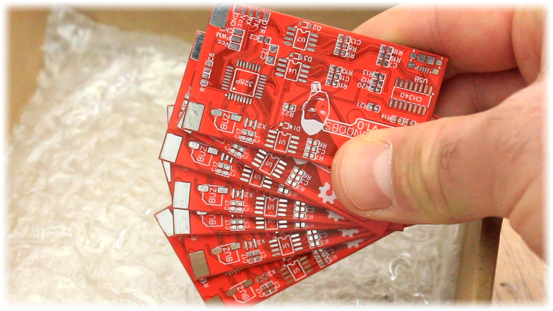
When you will download the GERBERS file above you will have a .zip file. Go to JLCPCB or any other professional PCB manufacturer, uplaod the .zip file and order your boards. In my case 10 PCBs cost me just 2 dollars plus shipping which for spain was 6 more dollars. I 7 days, I receive the next boards with a great look. You have silklayer for all the components so soldering the components should be easy. The PCB thickness is 1.6mm, signal tracks are 0.2mm and power tracks are 2mm. This red board has no exposed power tracks but the GERBER file you can download from above, is with the final version so don't worry.
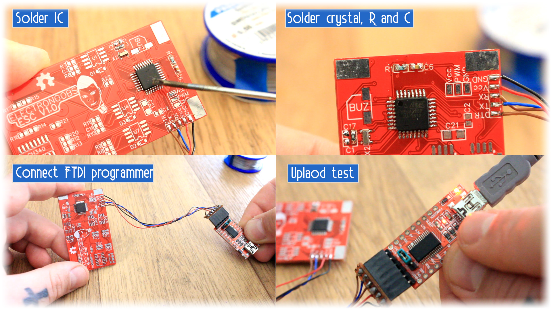
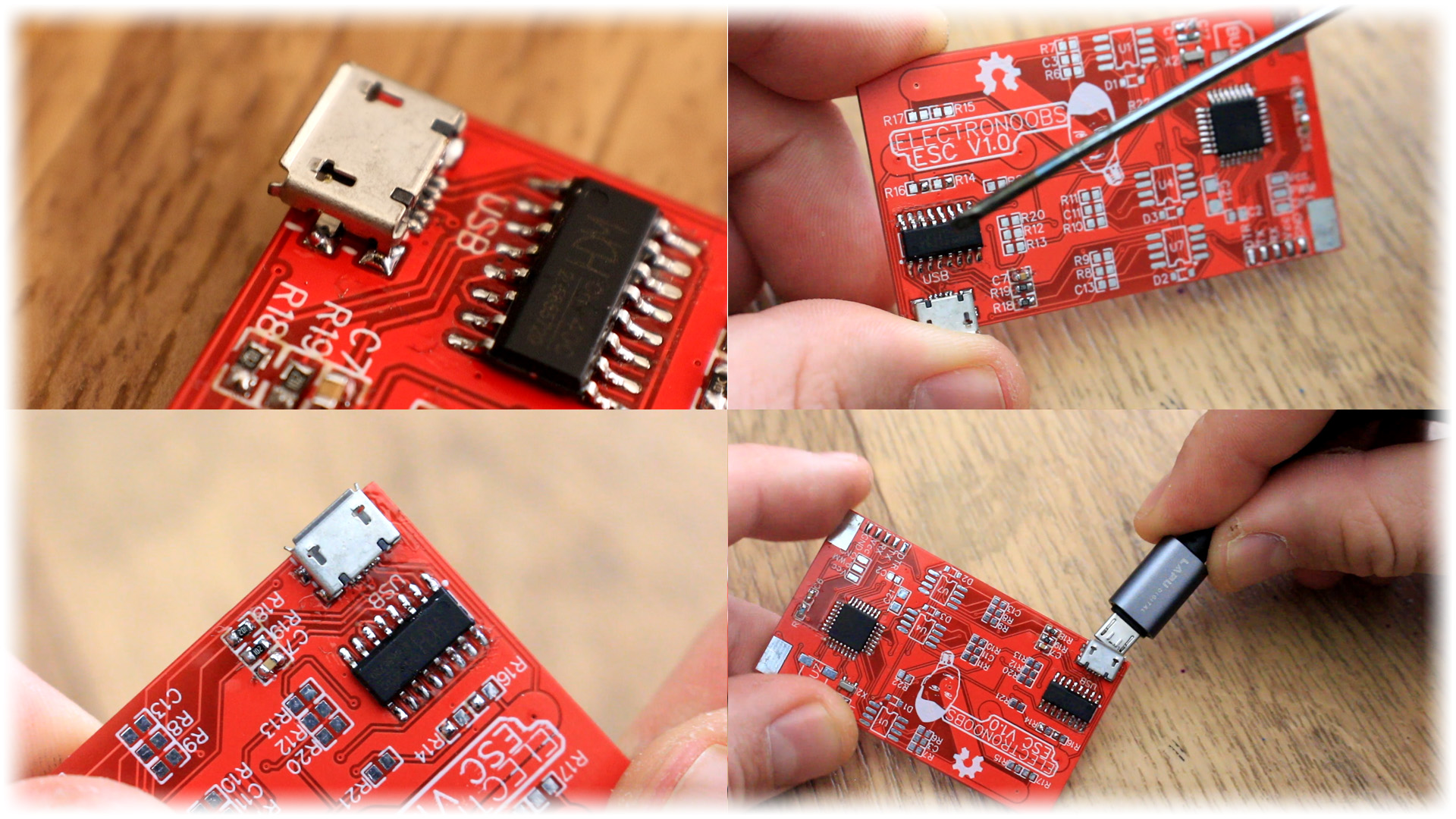
Once you have soldered all the parts for the basic configuration connect the FTDI external programmer to the RX DTR and TX pads but also Vcc and GND. Now open Arduino IDE and uplaod the next test code that will increas the "x" value each second and print that on the serial monitor. If you can see the number increasing, that means the IC was well soldered and it is working with no problem.
int x = 0;
void setup() {
  Serial.begin(9600);
}

void loop() {
  x = x + 1;
  Serial.println(x);
  delay(1000);
}