
 About me
  History
  Let's learn
  Contact us
  Arduino tutorials
 Circuits tutorials
  Robotics tutorials
 Q&A
Q&A Blog
Blog  Arduino
  Circuits
 Robotics
  Modules
  Gadgets
  Printers
  Materials
  3D objects
  3D edit
  Donate
  Reviews
  Advertising


PID control with arduino
Introduction.
A proportional–integral–derivative controller (PID controller) is a control loop feedback mechanism commonly used in industrial control systems. A PID controller continuously calculates an error value e(t) as the difference between a desired setpoint and a measured process variable and applies a correction based on proportional, integral, and derivative terms (sometimes denoted P, I, and D respectively) which give their name to the controller type.
In today project we will use this mechanism to control some brushless motor in order to calibrate our drone. We will put the motors on a balance and calculate the angle using the MPU6050 or the MPU9250 IMU module. So in our case the value that we will contro is the inclination angle of our drone. The e(t) error will be the difference between the raal angle of the drone and the desired one. The desired one will be 0, which means taht the drone is perfectly horizontal.
Part1. Building the balance
So let's say that you have already build the drone from the build your arduino drone project. But in that project we have use the multiwii platform for our flight controller. Now we want to make our own code to control the drone. But the drone won't fly steady unless we control each motor in a very precise way. That's why we have to learn how the PID control works. Each brushless motor will have a different power for the same PWM signal because motors are not perfect and they will never be the same. Fot that we have to constantly measure the angle of our drone, compare that value with the desired value and rectify the error if there is one.
So to tune our motors we will first build a balance for just 2 motors. This two motors represent just one axis, in this case will be the x-axis. As you know a drone can move in any of the 3D axis, x,y and z. All we want to do with this balance is to find our P, I and D constants. Each of this 3 constants will affect in one way or other the entire PID control, and we have to find the perfect ones. This is how we will proceed. For the balance we will need:
1 x 60cm (wood or metal)
2 x 80xm wood
2 x 22mm bearrings
1 x 20cm M8 threaded rod
4 x M8 nut
2 x regtangular piece of wood
1 x Big platform (recommended wood sheet)
wood screws...
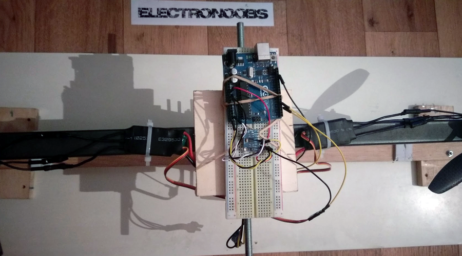
In the next photo we can see how to build our balance. Make a hole right in the middle of the 60cm bar and pass thge M8 rod through it. Add the bearrings and secure those with the M8 nuts, one on each side. Using two metal clamps attatch the bearrings to the two peaces of wood. Screw the entire systme to the big wood platform. Make sure that the entire system weighst more than 2Kg so the proppelers won't lift it. Add extra wood blocks to give it strenght. Also add some sponges or plastic band where the 60cm barr touches the wood in order to cushion the hit.
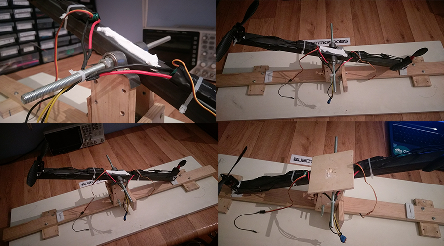
As you can see in the middle I've put a square sheet of wood . There is where I'll place the Arduino and the IMU module. Alos on each side, equaly distanced I've placed the two brushless motors with zip ties. The ESCs are tight in place using zip ties as well. Both ESCs share a commune 12 volts power suply with a male LiPo connector. To supply the entire circuit I've used an old PC power supply with a 12V output and 26A of current.
Part2. Circuit schematic
First of all place the brushless motors in the end of each side of the balance. Make sure that each of the motor is spinning in the direction shown in the schematic below. Also that the screw of the proppeller is geting thighten in the oposite direction as thew rotation, otherwise the propeller will fly away during the tests. If the motor is not spinning in the desired direction, just reverse teh top and bottom wires from the esc, leave the middle as it is. Make sure that the ESCs are calibrated and that both have the same scale. In this case this this ESCs both have a scale from 1000us to 2000us. If you don't know how to calibrate the esc watch this tutorial and use that codeto calibrate the ESCs. This is inportant. If the motors don't have the same scale, this system won't work.
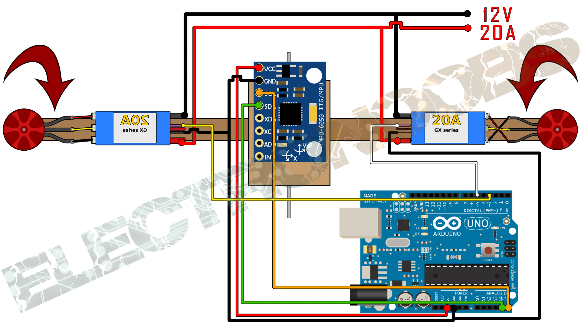
Now we should have the schematic above. Supply 12V to the ESCs. From the ESCs BEC supply 5V to the arduino or use the USB to supply it if you want. Connect the IMU using the i2c connection pins SCL and SDA. In the schematic below you can see with better details the mpu6050 connection to the arduino. Then connect pin 3 to the right ESC and pin 5 to the left one. Aslo connect gnd between the arduino and the ESCs.
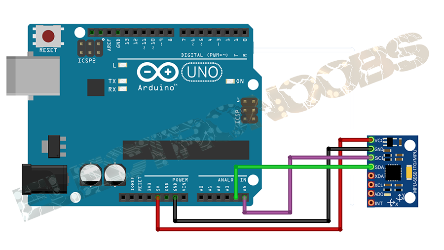
Place the MPU6050 module as centered as you can on the balance. I've use a breadboard to make all the connections. Alos I recommend you to wind each of the i2c cables around a GND cable. This will reduce noise of the i2c comunnicatin. For that get two wires of GND from the arduino to the MPU6050 and wire around each of this the SCL and SDA cables of the i2c. To equal the weight on each side I've used a magnet and place it closer or farther of teh center depending of the weight.Now that everything is ready to go we can start with the code.
Part3. Code
The code is not that complicated. We know that we have to read some data from the IMU (inetrial movement unit) module. Using that data we calculate the real inclination angle of the axis. We will use just one axis for the balance, the x-axis. We have to comparte that angle with the desired one which is 0º because we whant the drone to be horizontal. To contol the brushless motors we have to send a PWM signal to each ESC with a pulse with between 1000us and 2000us
because that is the range of the ESCs that we've calibrated in this tutorial.
We will divide the code in a few parts. I will try to explain the best I can each part. But first we have to know a little bit of mathematic. We will use some fomulas to calculate the angles. This are called Euler formulas. Go to the next page and continue with the tutorial.