Burn the bootloader to a ATmega328p AU SMD

When purchasing a new ATMEGA328P AU microchip they susually come with nothing burned into their memory. To program these microcontrollers you need to pre-burn a bootloader. The bootloader is like the microchip copan duro
ntroller. Without this controller the microchip won't understand the language we sent from the Arduino IDE. In order to understand the code we send, we have to burn a bootloader first.
Here I will show you how to burn a bootloader to a ATmega328p AU SMD chip using an Arduino NANO as ISP programmer.
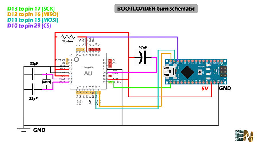
First of all we have to do the basic configuration of the microchip ATMEGA328P AU. The integrated won't work without that specific configuration. It will need the manufacture recommended circuit with a basic power source, decoupling capacitors, quartz oscilator and the necessary pullups resistors. In the schematic down below I show you the basic components and connections that have to be made for a proper functioning of the microcontroller.
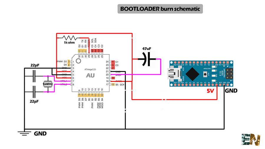
As you can see we have a 16MHz quartz oscilator between pins 7 and 8 of the SMD chip with two 22pF capacitors to ground. We have to connect ground to pins 3, 6 and 21 and a 5V supply to pins4, 6 and 18. Finnaly we add a pullup resitor of 1k ohms between 5V and the reset pin which is pin 29 of this SMD chip.It's recomanded to connect a 47uF capacitor between Aref pin and 5V.
Once we've done the basic circuit we'll have to make the following connections between the Arduino NANO and the smd chip pins in order to burn the bootloader to it.
Digital pin 13 from the arduino NANO to pin 17 from the SMD chip (SCK)
Digital pin 12 from the arduino NANO to pin 16 from the SMD chip (MISO)
Digital pin 11 from the arduino NANO to pin 15 from the SMD chip (MOSI)
Digital pin 10 from the arduino NANO to pin 29 from the SMD chip (CS)
Now we open Arduino IDE. We go to file -> Examples -> Arduino as ISP and we open the ArduinoISP example sketch. In tools we select Arduino NANO as a board, the COM of our USB connected Arduino and we upload the skecth as a normal one like any other to the Arduino NANO.

Once we've upload the ArduinoISP code to the Arduino NANO and with the previous connections we can burn the bootloader. For that we go to Tools -> Programmer -> Arduino as ISP as shown below.

All is left to do is go to Tools and pres burn bootloader. We will see the Arduino NANO lights are blinking a lot. Once it says bootloader burned we are done. We've sucessfully burned a bootloader to an SMD chip.
All we need to do now is test the chip for propper functioning. To do that we will upload a simple blink code using a FTDI conection as shown below. Don't forget to change the programmer back to normal.

Remember that we need a 0.1uF capacitor between the DTR pin of the FTDI module and our reset pin in order to program this chip.
I hope this tutorial helped you. Visit my YouTube channel to see more totorials and electronics stuff.
See arduino+RF controller tutorial here:

 About me
  History
  Let's learn
  Contact us
  Arduino tutorials
 Circuits tutorials
  Robotics tutorials
 Q&A
Q&A Blog
Blog  Arduino
  Circuits
 Robotics
  Modules
  Gadgets
  Printers
  Materials
  3D objects
  3D edit
  Donate
  Reviews
  Advertising