Arduino Persistance Of vision Clock

0. INTRO
Hi guys. Wellcome back to a new awesome tutorial. POV or persistance of vision refers to the optical illusion that occurs when visual perception of an object does not cease for some time after the rays of light proceeding from it have ceased to enter the eye. The illusion has also been described as "retinal persistence", "persistence of impressions", simply "persistence" and other variations.
In this project we will learn how to use a Hall sensor in order to detect rotations. We will count the time it takes to make a full rotation of the POV propeller and by dividing the measured value by 360 we get time per degree. Next, with a smart code we decide when to turn on and off a line of LEDs in order to draw shapes in the air. The propeller will spin fast enough so the human eye won't be able to tell the difference and we will se an imaginary fixed shape. So let's get started.
1. Component list
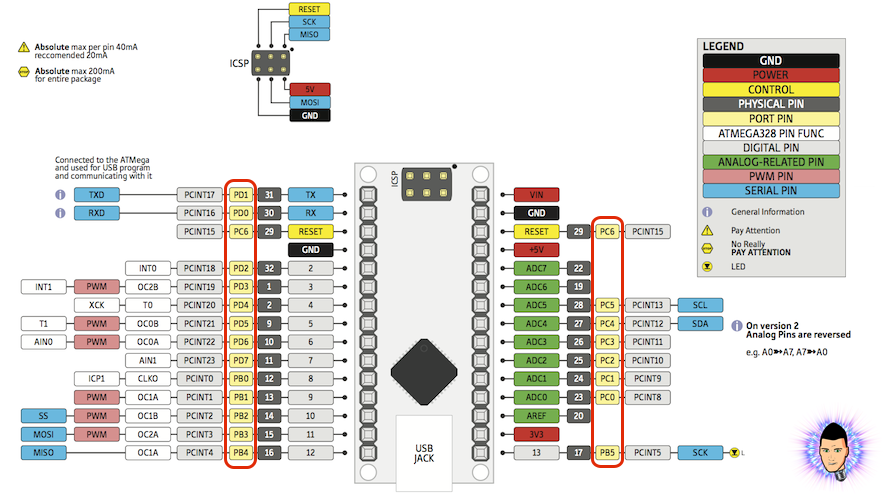
Ok guys so our project is restrained to th amount of digital outputs the Arduino NANO or promini has. In this case we will use pins D2 to D13 of the Arduino since pins D0 and D1 are the Tx and Rx pins and we can't solder anyting to those and be able to upload code after that. If we look in the port map below of the Arduino with the ATMEGA328p chip, we see the ports for each pin.
portC (analog input pins)
portD (digital pins 0 to 7)
We will use a total of 11 LEDs. I've used 8 green LEDs for the hour/minutes lines. Two red LEDs for the hours points and a blue LED for the border circle. For each LED we need a 100ohm resistor. We will also use a A3144 hall sensor switch with a 10K ohm resistor pullup. You could use both Arduino NANO or the Arduino proMini with 4V adn 16MHz speed. Finally we need some drilled PCB, wires, a 7.4V 2S LiPo battery, a sliding switch and the 3D case that I've designed. Use the link below for the full part list and also the download link of the 3D printed case for this project.
Full part list here
2. The schematic
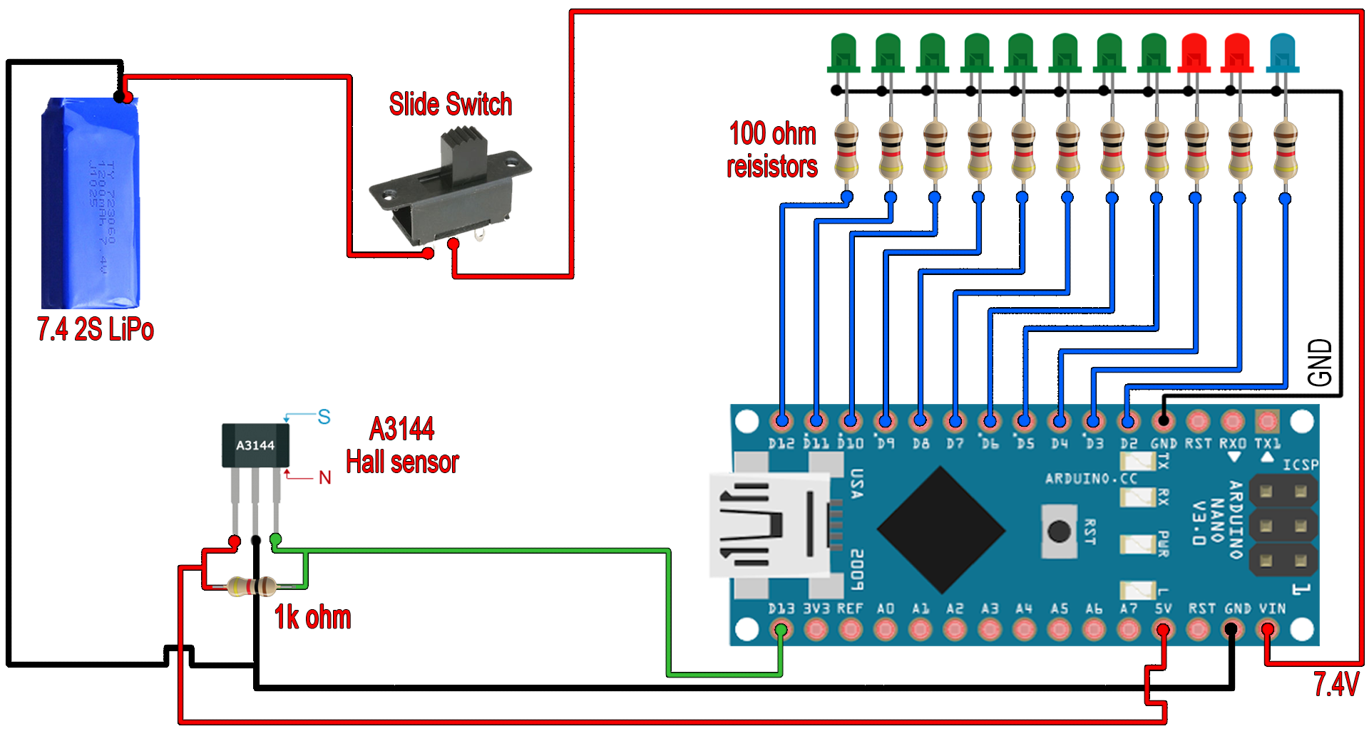
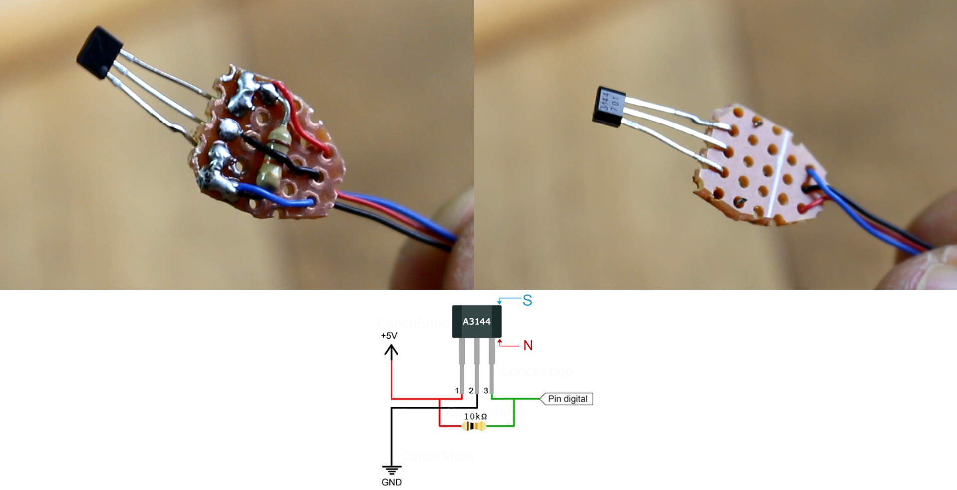
Check the schematic below. Download it and have it in front of you while soldering. As we can see we have our hall sensor connected to a pullup to 5V from the arduino. The signal pin from the sensor (pin 3 of A314) is connected to digital pin D13 of the Arduino. On this pin we will generate pin change interruptions. Next we have 11 LEDs connected to pins D2 to D12 each with a 100 ohm resistor to limit the current. To supply the entire circuit I've used a LiPo 7.4V battery and a sliding switch to power everything up. Use some male pins for the battery if you want to take it out later for external cahrging.
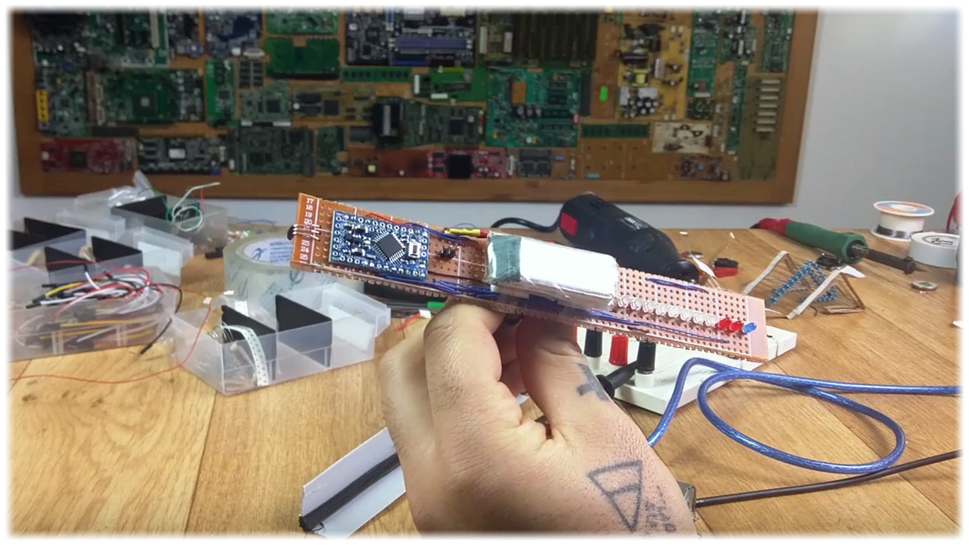
You could solder everything on a drill PCB as I first did for my first prototype you can see below or download the 3D case I've designed and place everything inside it.
3D printed case here
3.1 Building the support
You have the files for the 3D printed parts in an STL format in the link above. These files include the main case, the back lid, the motor support, the two legs for the bearing and the top bearing supports. This should be the final shape of the entire project. Use M3 screws and nuts and fix everything in place.
On a wood plate place the two 3D printed legs with M3 screws. On a M8 large screw place the main case with nuts and washers.
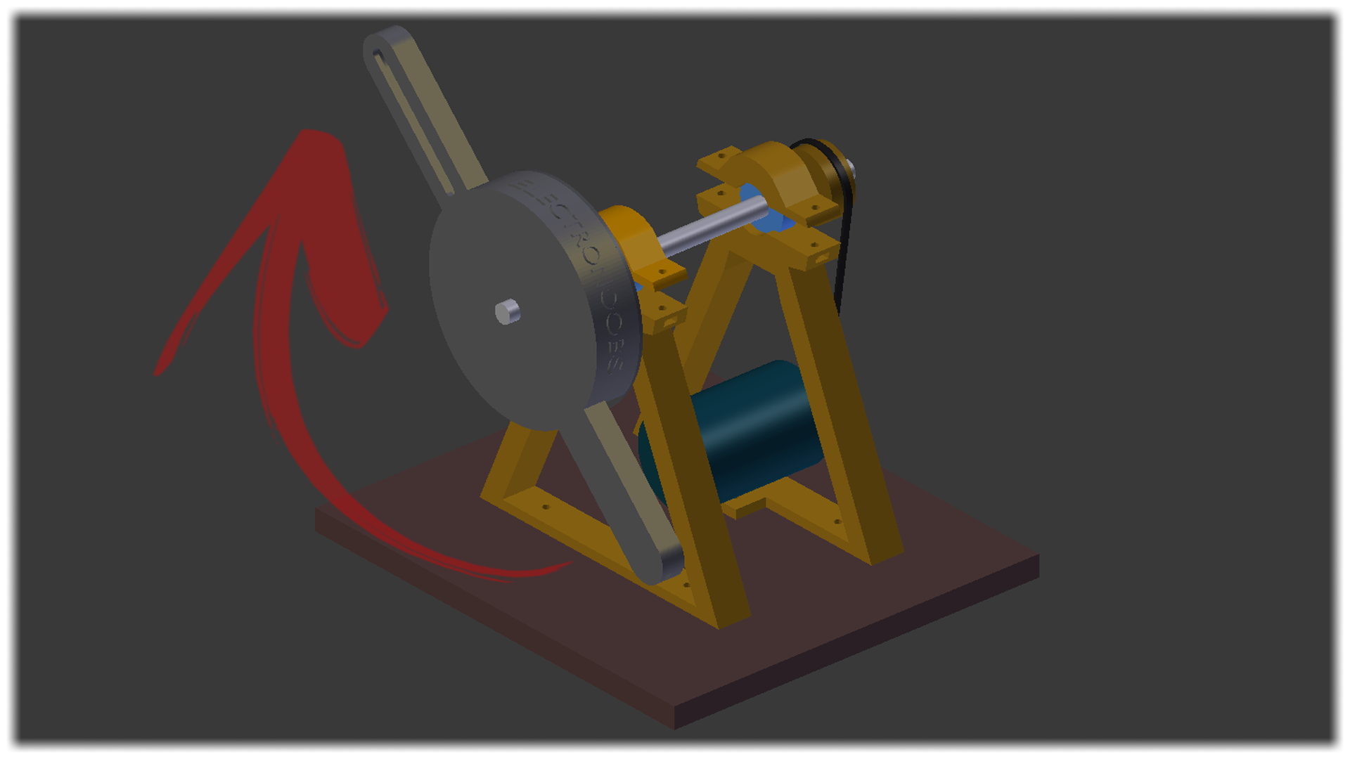
Inside of the main case we will palce everything once soldered. Remember to ad the back lid and on this glue the sliding switch. On the fron line hole we will place the 11 LEDs and on the other side hole the hall sensor on the exterior of the case. The DC motor placed belwo and a connection between the motor and M8 screw pulleys. That's it. Now let's solder everything and place it inside and then look at the code.
3.2 Soldering everything
First of all on a small pice of drilled PCB I solder the 8 green LEDs' follower by the two red ones and finally the blue one. Each with its 100 ohm resistor and a wire long enough. The short pin of each LED is the negative pin and all the LEDs share GND on that pin.

Now glue the small PCB with the LEDs on the interior of the case and solder each of the wires to pins D2 to D12 of the arduino. Alos solder the GND wire from all of the LEDs to the GND pin of the arduino. Don't use too large wires so shortehn each LED wire so it will fit almost exactly.
On the other side solder a 1K ohm resistor between 5V and the signal pin of the A3144 hall sensor. Also share GND between the middle pin of the A3144 and the Arduino GND pin. Finally solder the signal pin to digital pin D13 and we are done.
The last aprt is to glue the sliding switch on the 3D printed lid and solder two wires. One from the LiPo to the first pin of the switch and another from the Vin pin of the Arduino to the middle pin of the switch. I've added an extra two male pins so I'll be able to disconnect the battery for external charging.
Also remembre to glue the samll magnet on the bottom support so it will always be in front of the Hall sensor while spinning. I've used hot glue to to that as you can see below.
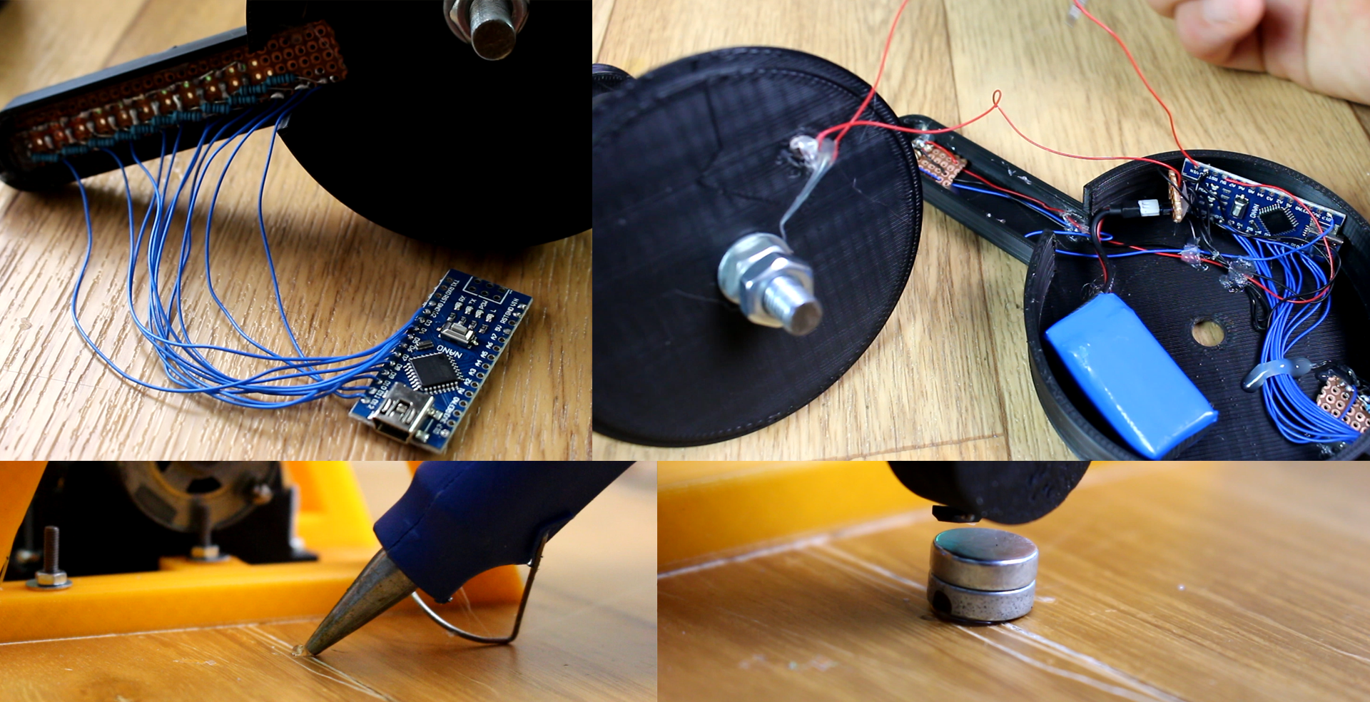
Don't close the case till we upload the code. Make sure that everything is well fixed in place with glue and that the propeller is balanced. For that it should always be horizontal when is not spinning. Add extra weight in order to balance it. Let's get to the code part on the next page.

 About me
  History
  Let's learn
  Contact us
  Arduino tutorials
 Circuits tutorials
  Robotics tutorials
 Q&A
Q&A Blog
Blog  Arduino
  Circuits
 Robotics
  Modules
  Gadgets
  Printers
  Materials
  3D objects
  3D edit
  Donate
  Reviews
  Advertising
