
 About me
  History
  Let's learn
  Contact us
  Arduino tutorials
 Circuits tutorials
  Robotics tutorials
 Q&A
Q&A Blog
Blog  Arduino
  Circuits
 Robotics
  Modules
  Gadgets
  Printers
  Materials
  3D objects
  3D edit
  Donate
  Reviews
  Advertising


Mini CNC plotter

1.
2.
3.
4.
5.
6.
7.
Intro!
We will see how to build our own 3D printer. This will be a prototype, but once you manage to build it, you'll probably be able to build much larger and much more acurate printers. The principle is the same. We will use step motors to control the movement of the 3 axes of our machine.
CNC - What is it?
The system is based on controlling the movements of the working tool relative to the coordinate axes of the machine, using a computer program executed by a computer.
In the case of a lathe, it is necessary control the movements of the tool in two coordinate axes: the X axis for the longitudinal displacements of the carriage and the Z axis for transverse displacements of the tower.
For milling vertical displacements, corresponding to the axis Y. This servomotors are incorporated in the mechanisms of the carriage and the turret, in the case of lathes and in the table in the case of control also milling machine; depending on the capacity of the machine, this may not be limited only to three axes.
Step motor - What is it?
The step motor is an electromechanical device that converts a series of electrical impulses in discrete angular displacements, which means it is able to move a number of degrees (step) depending on your control inputs. The stepper motor behaves the same way as a (D / A) converter and digital-analog can be governed by impulses from logical systems.
This motor has the advantages of precision and repeatability as positioning. Its main applications stand out as variable frequency motor, DC motor, brushless servomotors and digitally controlled motors.
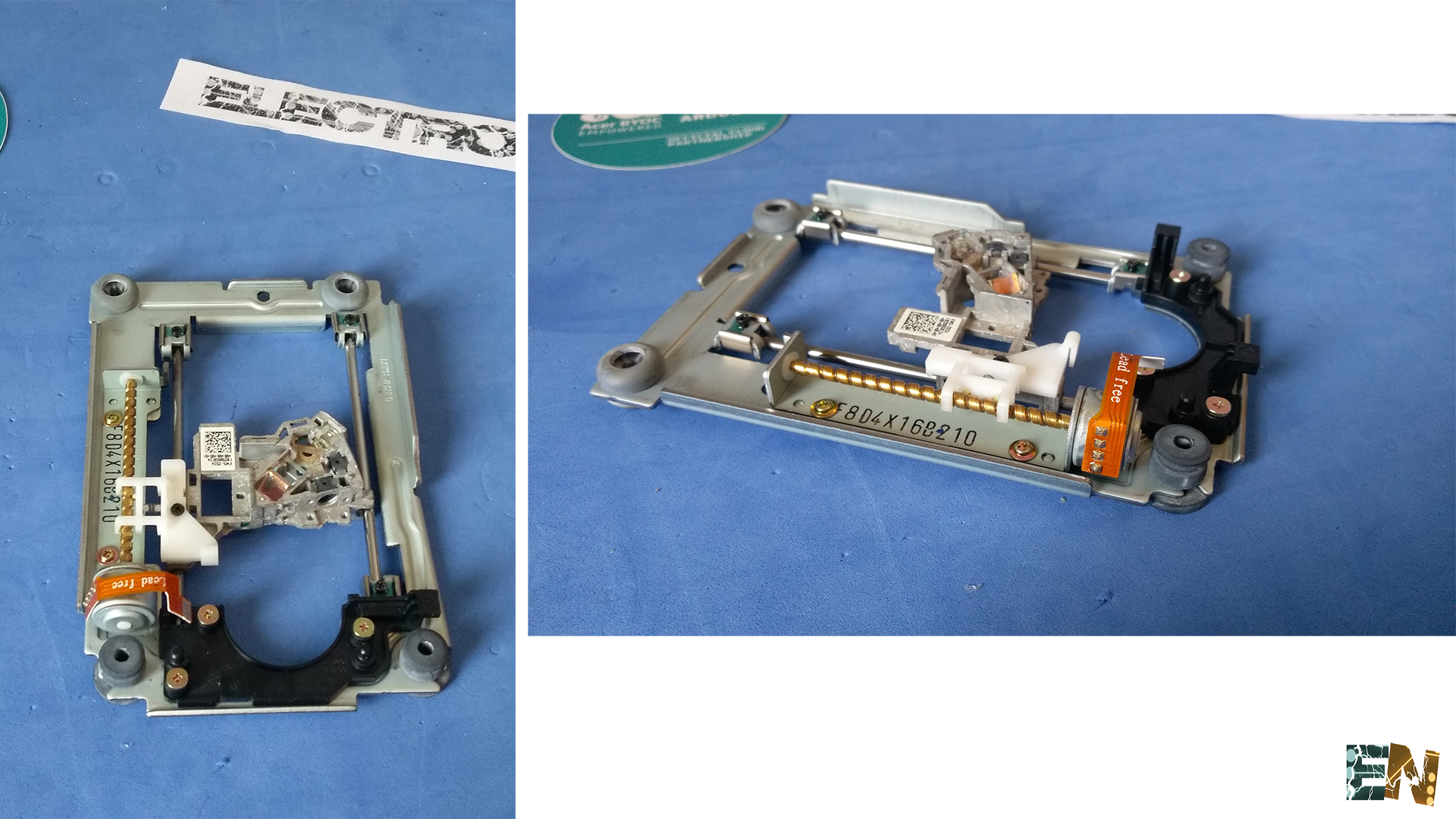
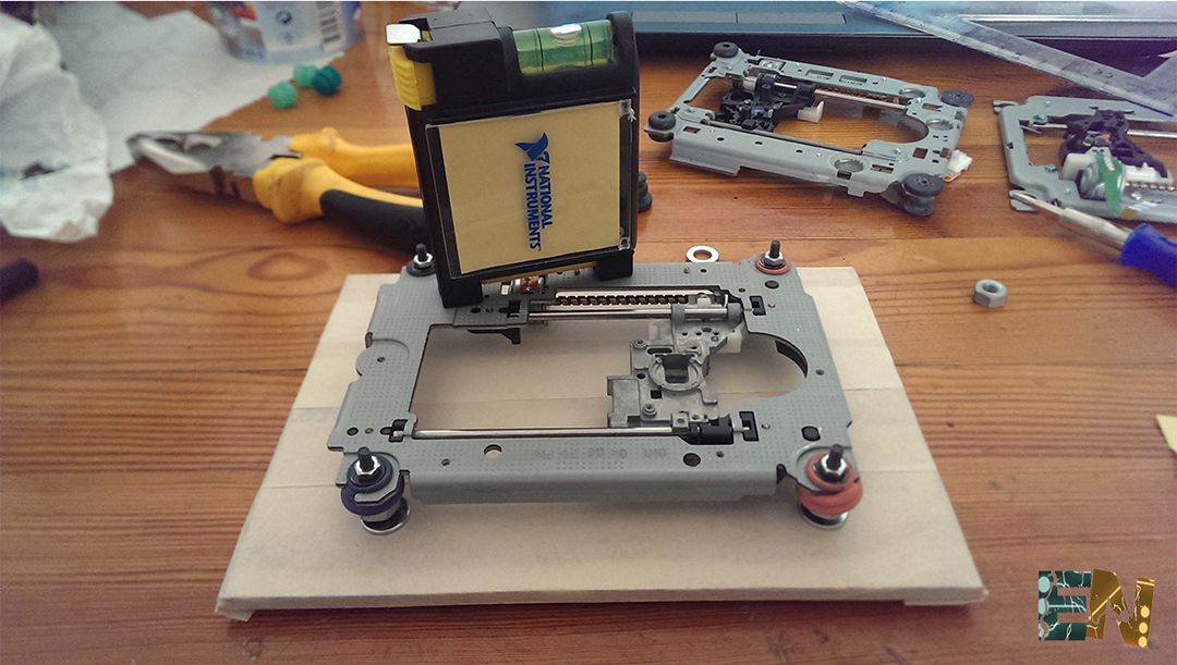
First of all we must open 3 DVD recorders to remove the motors and moving parts necessary for the construction of our machine. We must open them with care not to break the pieces we need. In the next picture we see the inside of a DVD recorder.
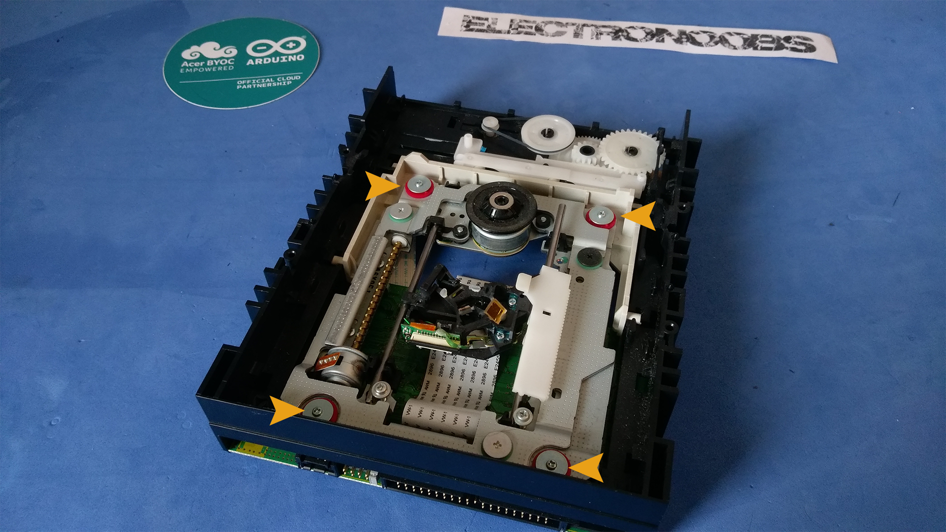
Simply unscrew the 4 screws marked on the image can extract the piece we need, an entire axis by a stepper motor. We can see in the image below the piece just removed.
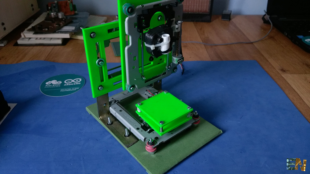
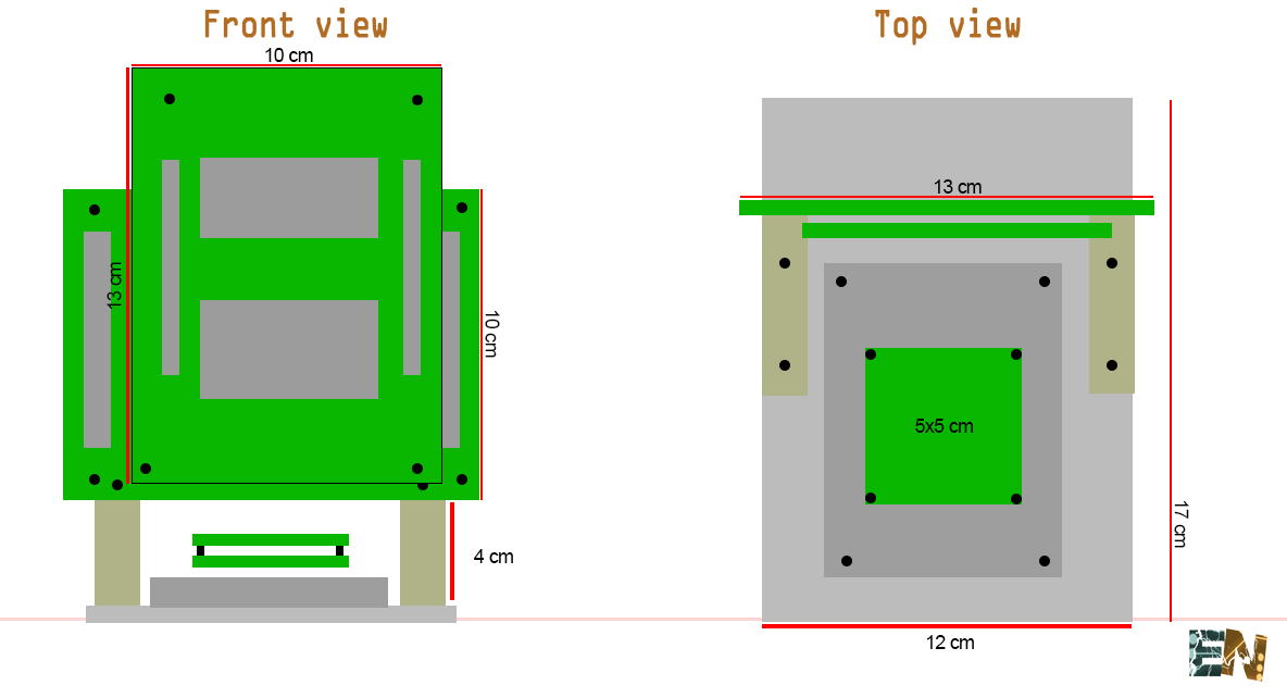
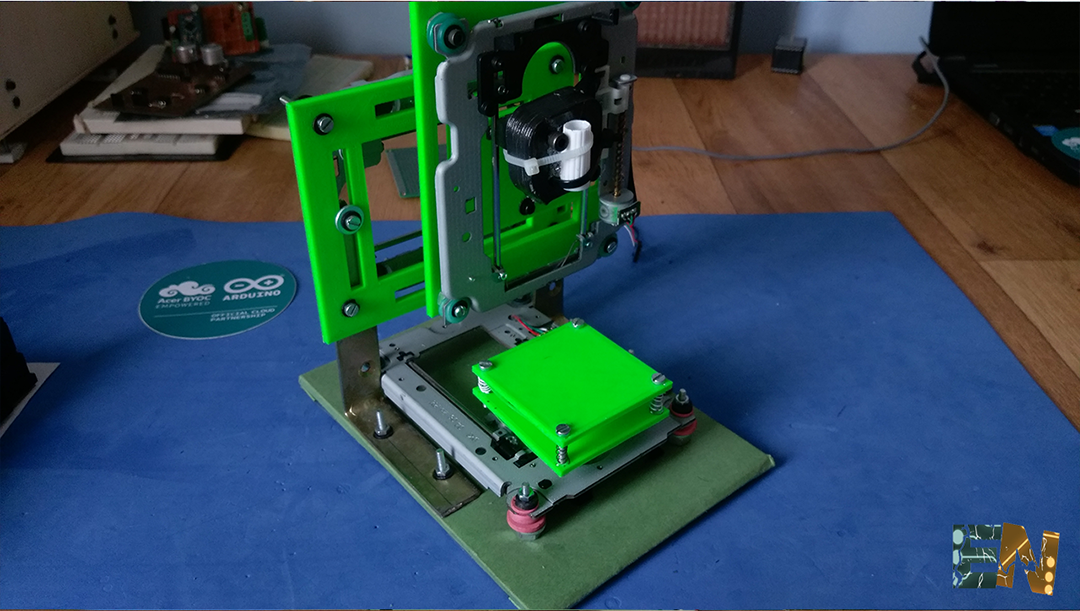
Now we have 3 axes we need, we build the machine itself. Before you start you can see my machine sizes in the image below.
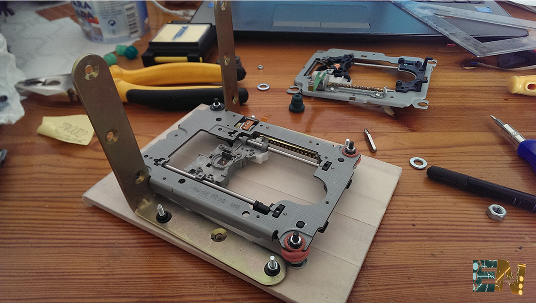
That cut a wooden plate 12x17 cm will be our base. 4 holes will very focused in the right way to screw the first axis, which is the axis "y". We check that the holes in our plate match those of the shaft out and screwed recorders 4 screws.
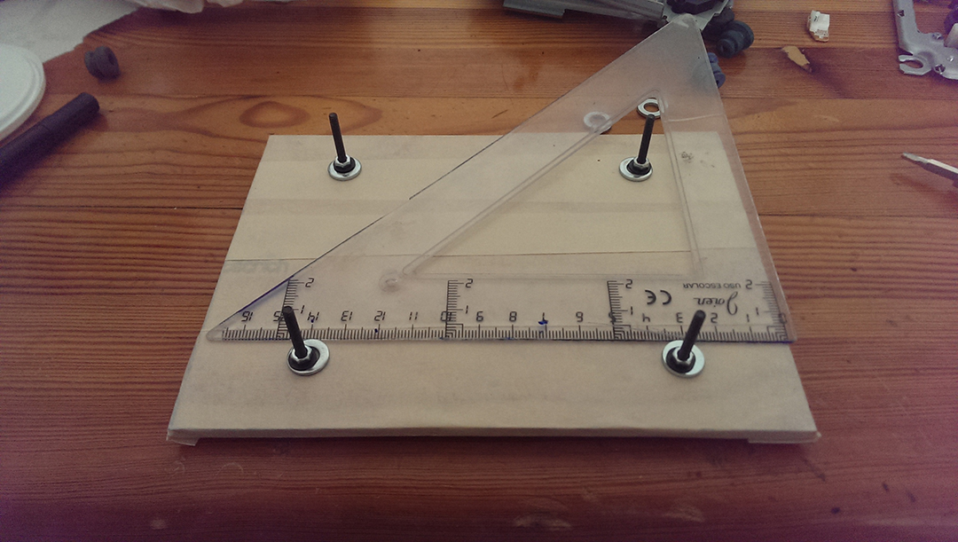
Before we add the axis spacers on each screw, so you have a small space between the engine and the base.
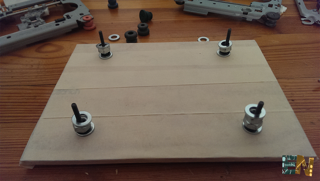
We put the shaft in place and making sure at all times that you screwed this perfectly horizontal well.
The next step is to add the "Z" axis. For that we will use two 90 degree angles. The we screwed in place as seen in the picture below.
For the next step we download and print the file to the "X" axis. If you do not have a 3D printer simply cut another wooden plate with the dimensions given above. This plate is screwed along the axis "X" to the two angles of 90 degrees.
Download the
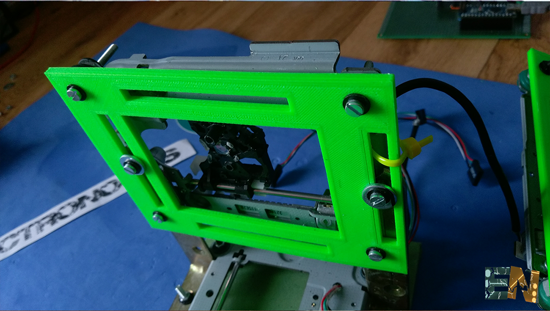
As you can see in the picture below 3 holes have been made in the "X" axis to add the axis "Z" that will make the movement up and down.
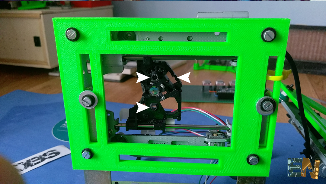
Now we print the plate to the axis "Z". If you have 3D printer will have to cut a wooden board too. We screw the 3 screws and introduce them into the 3 holes previously made.
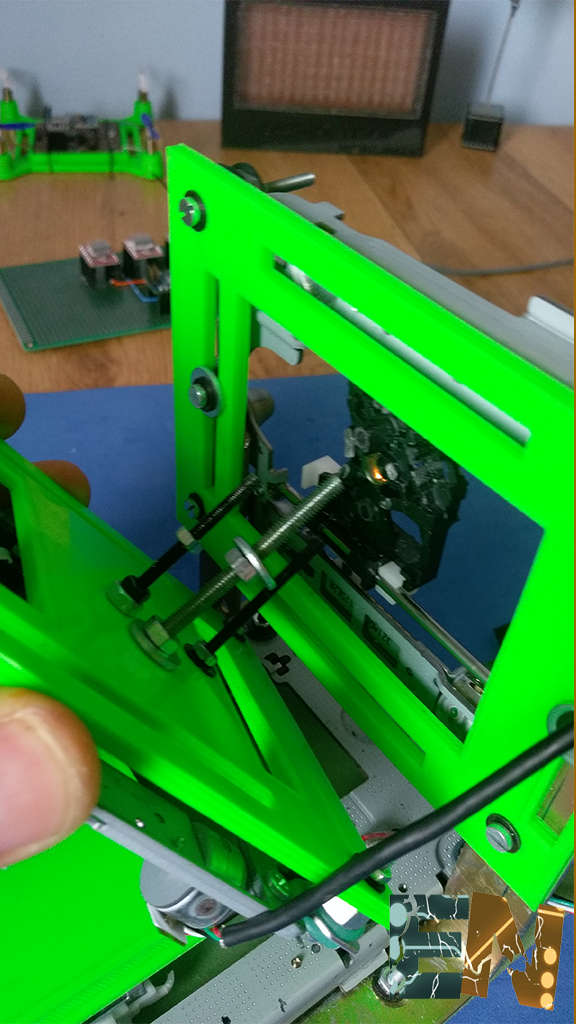
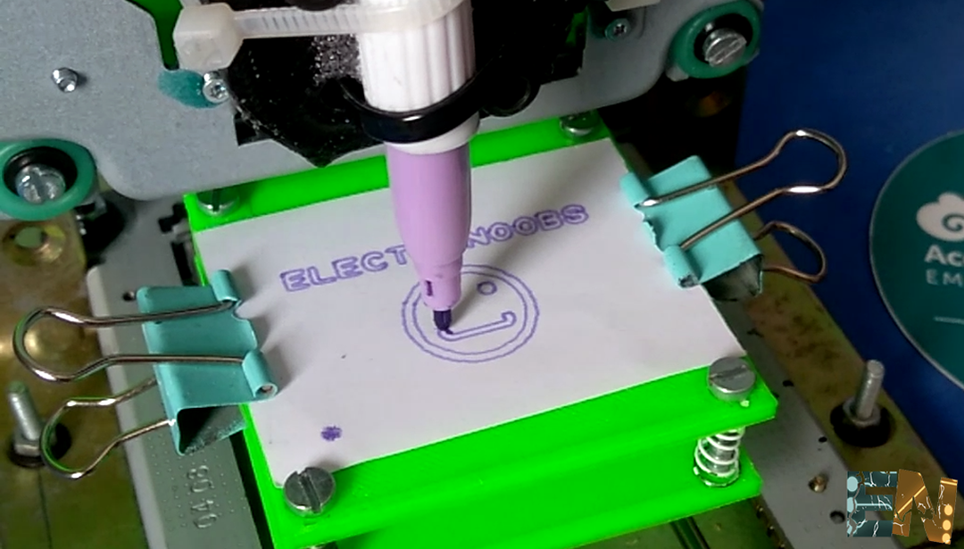
We're ready. Print or double table we made the "Y" axis where printing is done, add a cap of a pen on the axis "Z" and we're ready. We will pass below the electronic part.
Download the
Download the
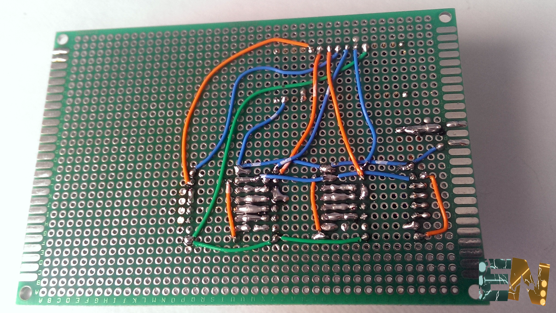
We already have the physical part mounted. We turn now to the part of elctronica. Before programming must mount the circuit for GRBL. Here you can see the complete schematic using a microcontroller Arduino NANO, 3 drivers A4988 stepper motor and few extra components.
Download scheamtics here:
GRBL schematic !
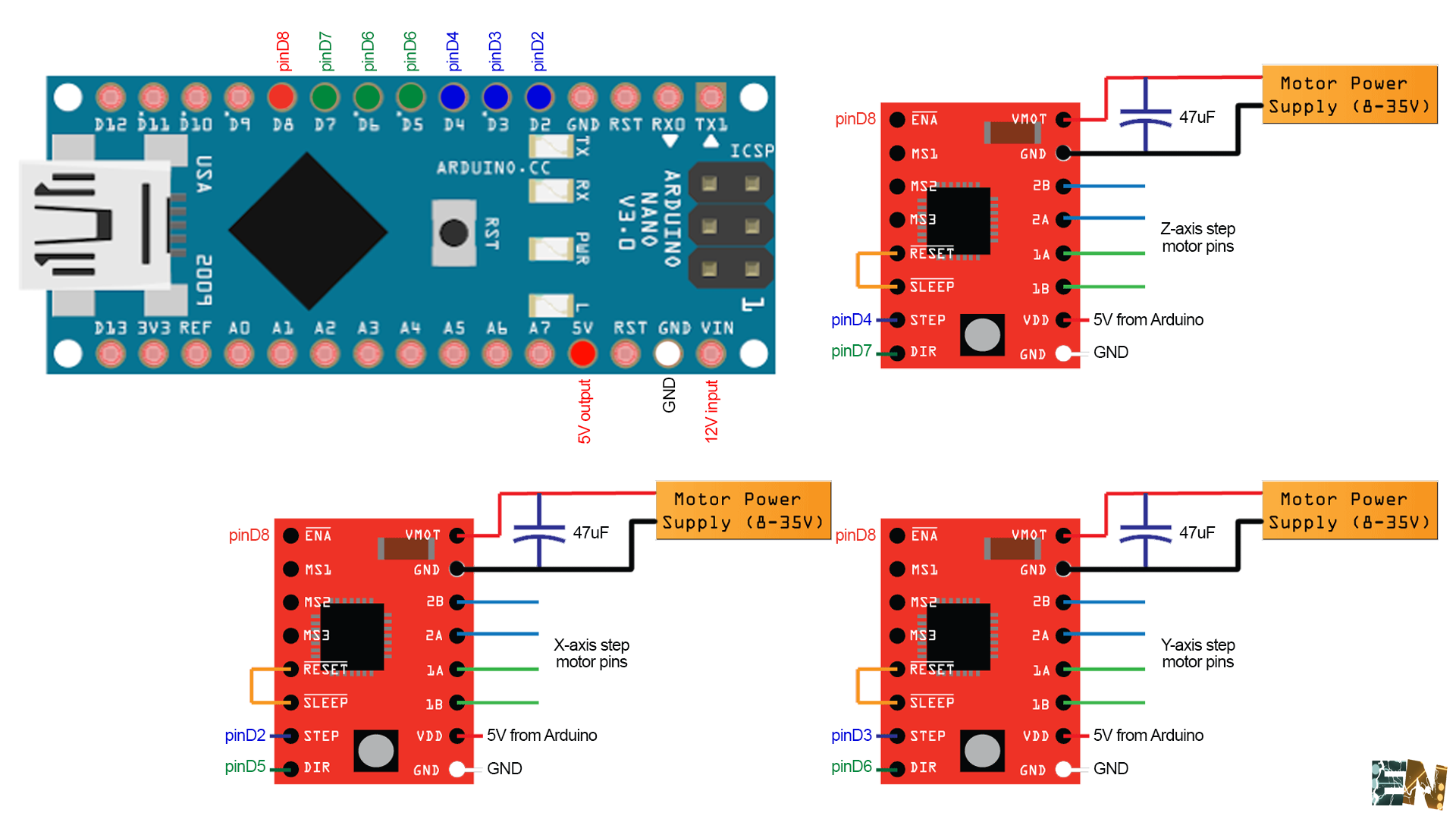
We use digital pins 2, 3 and 4 to give the number of steps we want to do each engine. Digital pins 5, 6 and 7 will use them to choose the direction of rotation of the motor. With the digital pin 8 will activate the motors. Arduino will feed through its Vin input pin to 12 volts. The arduino nano carries a voltage regulator 5 volts so no siemprer problem that we do not apply more than 16 volts at its input Vin. Will feed 12 volt modules each with a capacity of 47uF between Vin and GND to provide load when necessary. Each stepper motor has 4 inputs. Input A1 A2 and B1 B2. Connect these inputs of our modules and engines are ready.

We see in the photo above that using a double layer PCB we added the female pins required to connect the arduino nano has 26 pins, 13 of each side 6 rows separated from each other. Then we started to add the female pins to a single module A4988 which has 8 pins on each side 6 separated from each other. Then we will add 4 rows of pin female more for the other two modules.
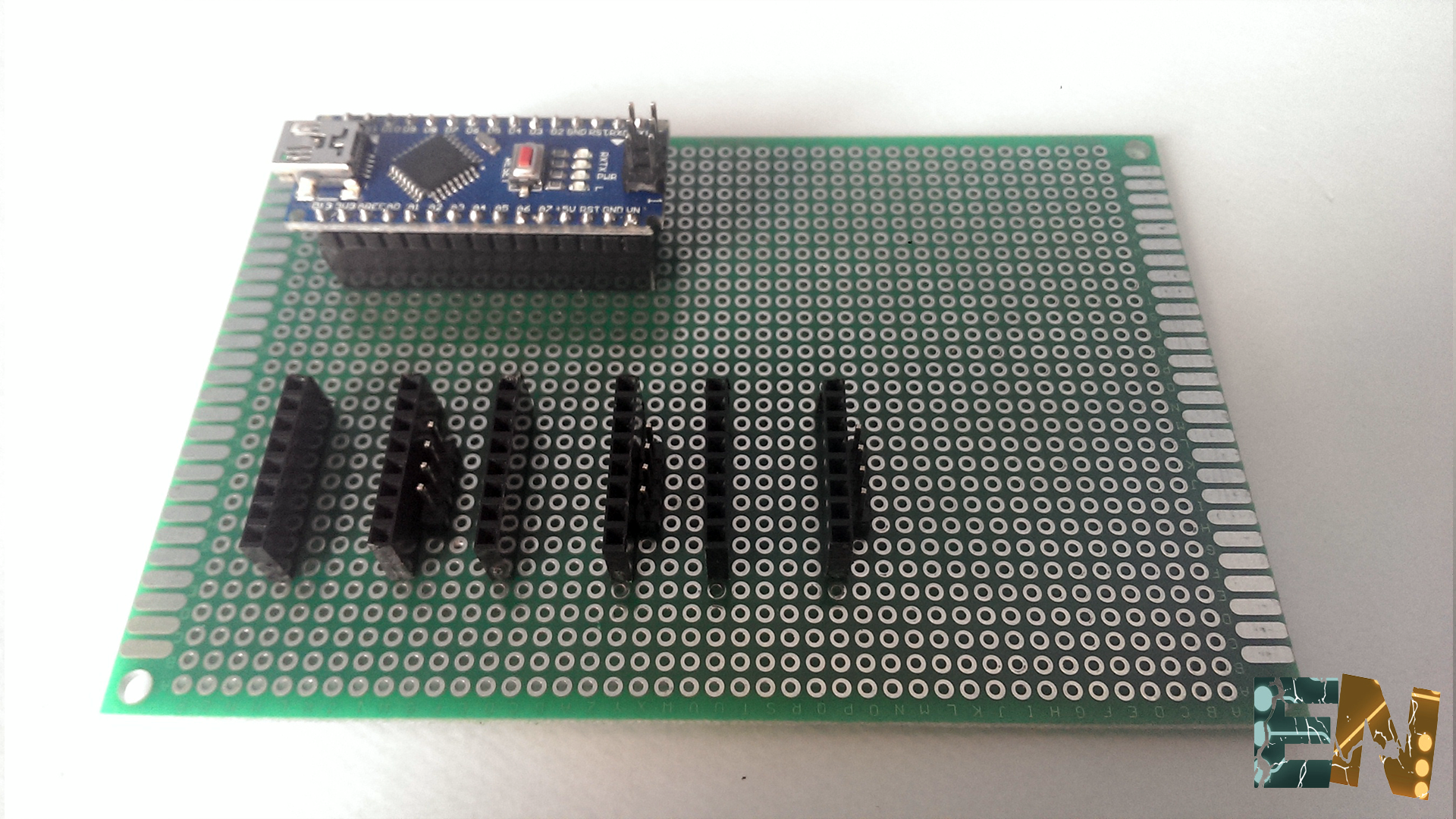
We see in the photo above we have not only added the female pin modules but also 4-pin male for each exit to the A1, A2, B1 and B2 engines.
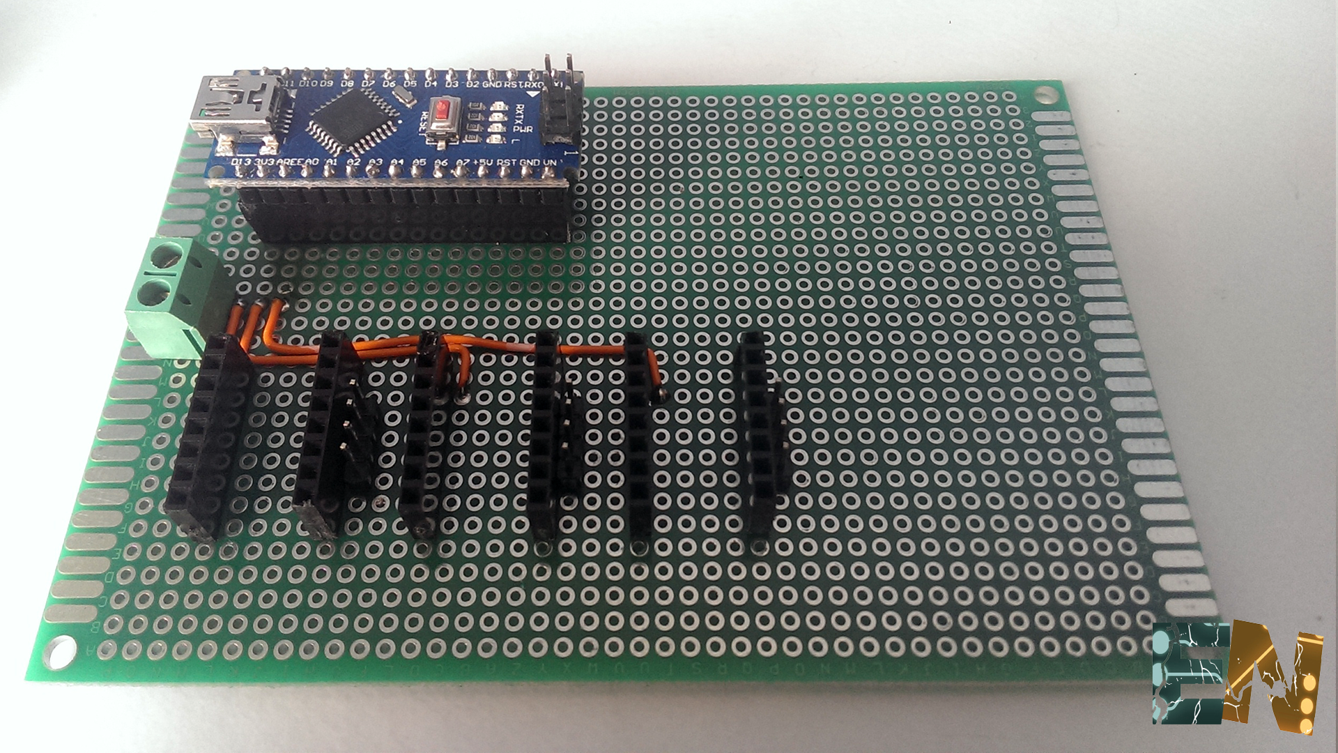
We have added a connector for input of 12 volts. Fed with small wires 12 volts and ground modules and also to arduino. Then do all the wiring according to the schematic utilizand wires and tin in the best possible way. Very carefully when feeding modules as Vimot A4988 is 12 volts or more since it is the voltage applied to the motor but Vdd is 5 volts from the Arduino and that will be the internal operating voltage of the module.
We are now ready to load our GRBL program the Arduino. That cnectamos with the Arduino USB to a PC. The links below will download two programs. The first will Xloader that is the program you use to load the firmwere GRBL the arduino. For that we must download the .hex file below. Download the files and move to the next step.
Download Xloader:
Download GRBL.hex:
Dwonloaduniversal G-code Sender 32-bit:
Download universal G-code Sender 64-bit:
You have already downloaded files and the PC connected to the arduino. The next step is to start the program XLoader
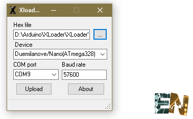
A platform as above photo should appear. We pressed the three ellipses and seek the GRBL.hex file you just downloaded. Entities that what should UnArchiving. Open the file with the .hex Xloader. As a model we choose arduino Demilanove / nano as it is what we use. We choose the COM. In my case my PC has assigned my arduino in COM9. We tightened up and watched as the LEDs TX and RX Arduino serial bus start flashing. Once we uploaded the program we are ready to send code G. For this use the following program that is downloaded heemos Universal G-code Sender. 3 motors connected to the PCB correctly. We feed plate with 12 volts and connect the USB to arduino. Start the Universal G-code Sender.
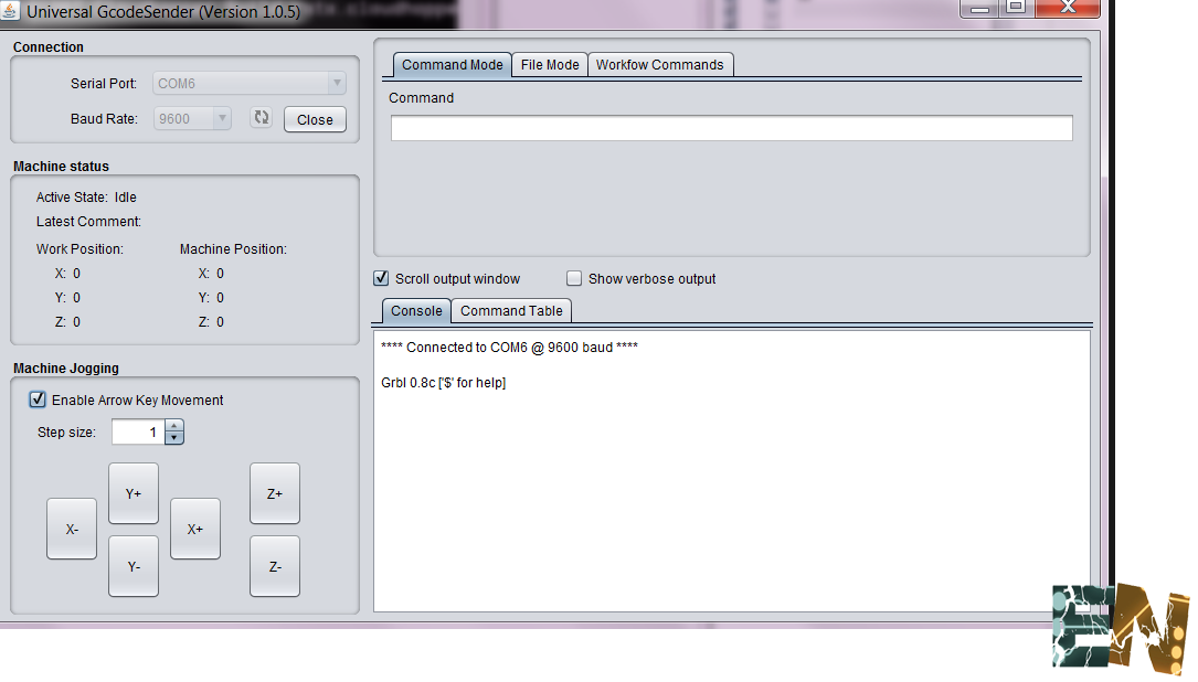
In the section of the COM connection select it and click open. We observe the console as a communication generated with our arduino. At this moment we start tapping the buttons for manual control engines should move. To test go to the file mode (file mode) and open the following file ejemplo.gcode. We opened it and pressed send and see how the machine began to draw. Do not forget to add a small paper and a pen for drawing.
Download example.gcode:
See more tutorials here :