I want to power on my microcontroller for a short time, do a process and then go back to sleep where it consumes 0 apms of current. I’ve done something like that with the ultra-low power mode a few months ago on a different project, but even so, in that mode I was still consuming around 90uA. So, if I were to use a battery, after a year or so, the battery would get empty. I want to completely power OFF the system after the process is done and power up again when a new input is detected, for example I detect that somebody opened the door with a vibration sensor. For that I will use a latch circuit and that’s what I want to show you today. A circuit that enables power with a push of a button, and then, could be turned off by the microcontroller itself. I will show you step by step how this circuit works and how to implement it, and of course, see the results in power consumption.
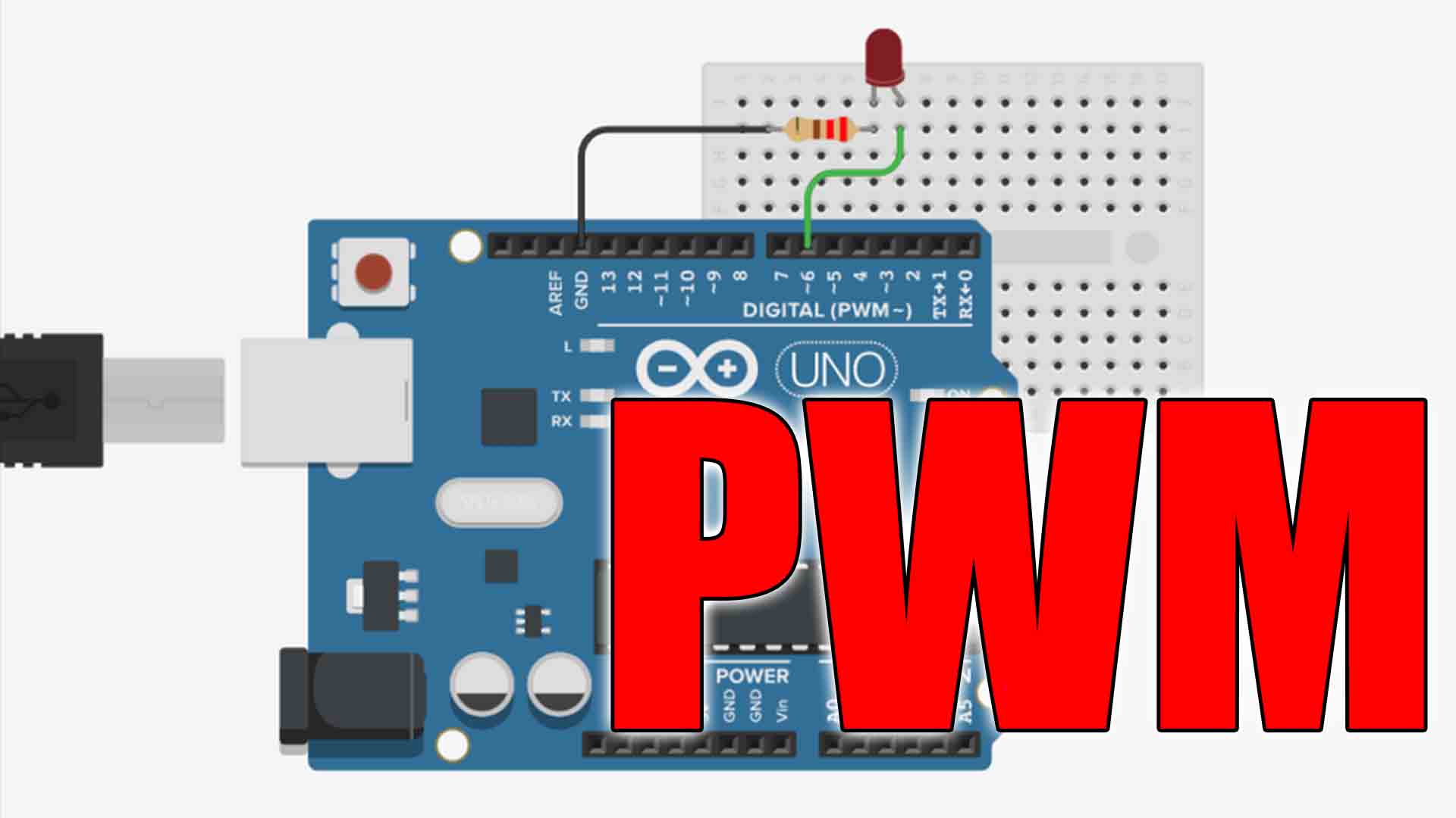
Below you have all the parts needed for this circuit, and on the next step you have the schematic. You can test this circuit on a breadboard or maybe solder it directly to a small prototyping PCB. You can also add an extra LED with a 100 ohm resistor at the output, so you can see when the output is ON or OFF.
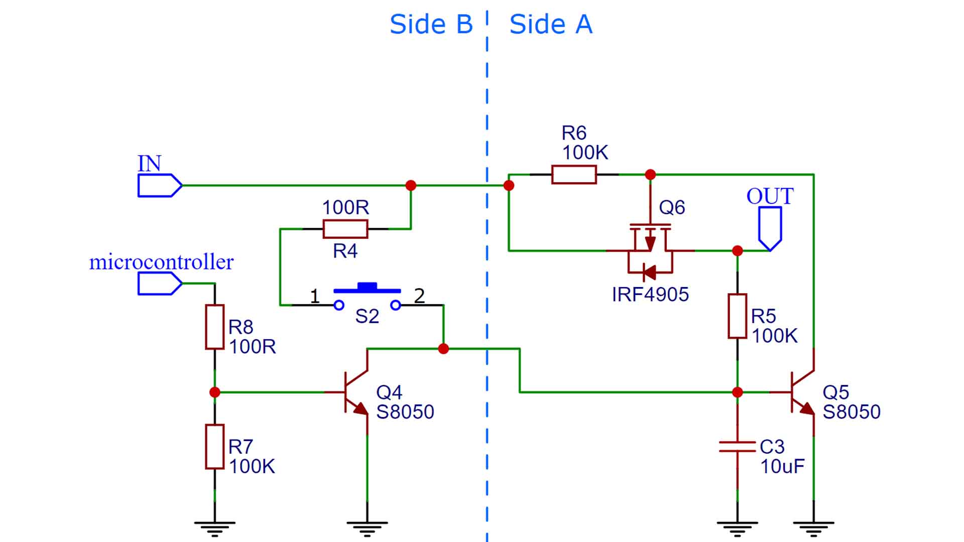
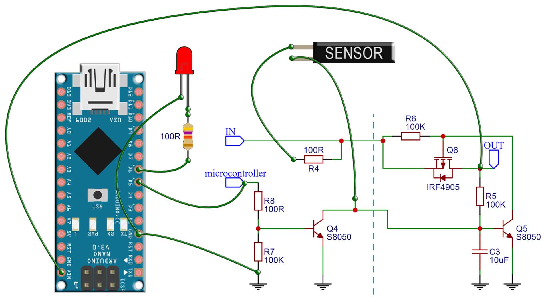
Below you have the schematic I've used. When you power the circuit, all transistors are OFF. The Q6 P-MOSFET is the one that enables the output, so the current path from IN to OUT. Let's center first on the Q5 BJT transistor. When you push the button (or sensor), as you can see, that will connect the R4 to the base of the Q5 transistor. Since R4 is a pullup connected directly at the input, this will turn ON the Q5 transistor. Since Q5 is now ON, there is a path to ground from the gate of the Q6 MOSFET. Since that is a P-type, it will now turn on because we have connected its gate to GND. So the output is now ON, great. The output is latched in the ON position becasue even if the button is not pressed anymore, we now have the output from the cicruit connected at the base of Q5 with a 100K resistor and that would keep Q5 turned ON and by that the output stays ON.
So how do we turn this circuit OFF? Well, we use Q4 for that. If we activathe this bjt transistor, it will connect the base of Q5 to GND and by that, it will turn OFF the gate of the P-MOSFET and by that turn OFF the entire circuit. So all we have to do is to connect the Microcontroller digital pin to the base of the Q4 transisitor and when we put taht pin HIGH, it will turn ON Q4 and by taht turn OFF Q5 so the output is now LOW. We use C3 capacitor to give a small delay till the circuit can get ON or OFF.
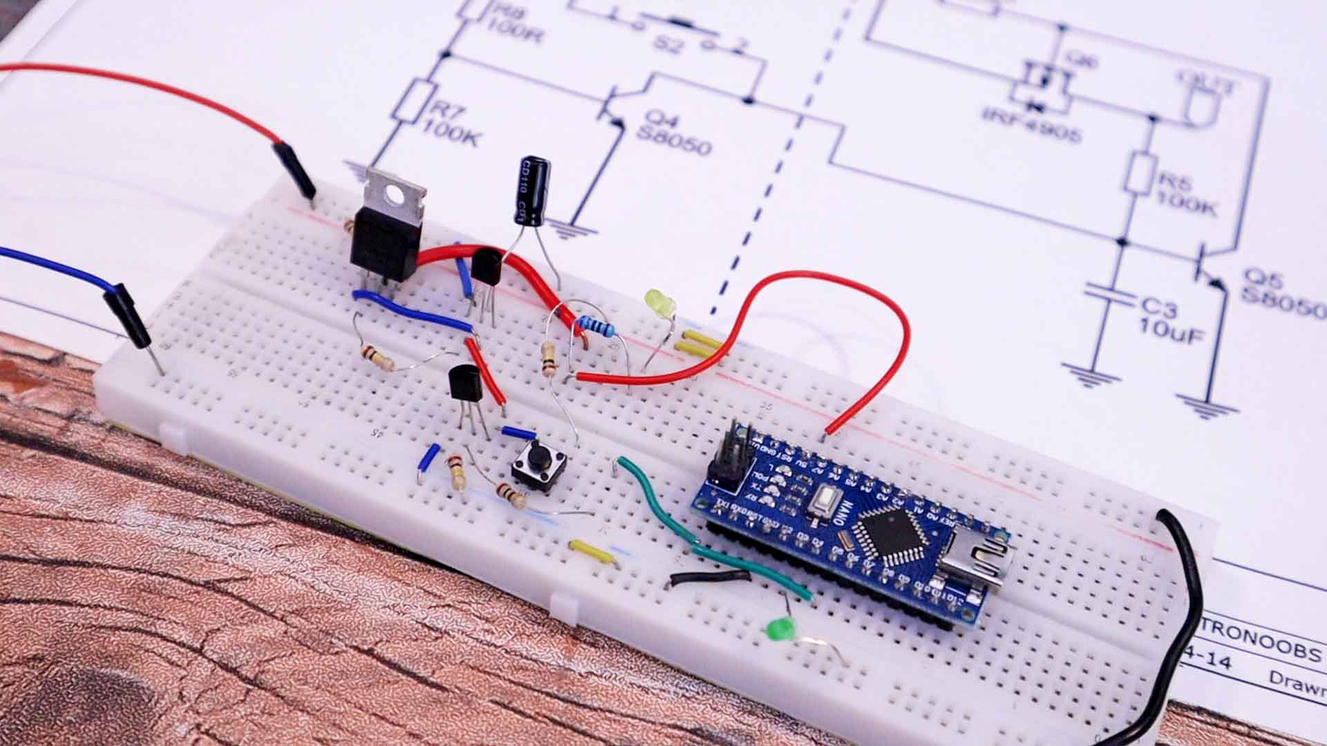
Ok so now, instead of the push button I add my vibration sensor between the input and the base of Q5 transistor. This has two connections inside that will touch when the sensor vibrates. So it will clsoe the circuit with that, just as the push button. The output from the latch circuit si connected to Vin pin of the Arduino, so when the output is HIGH, the Arduino will turn ON. Also remember to share GND between the Arduino and the latch circuit and supply. I connect digital pin D5 from the Arduino to the R8 of the latch circuit and we will use this pin to turn OFF the circuit. To simulate a process, I will use the LED connected at pin D6 and blink it 3 times.
Copy the code from below and upload it to the Arduino. As you can see, is very important to first set to low D5 and then do your process. Otherwise that pin wouldn't have a defined state and might activate the latch circuit and turn off the output. So set the pin to low and then make a process (blink the LED in this example). Finally when we set D6 to high, ot will enable Q4 transistor and with that turn off the circuit.
void setup() {
  pinMode(5, OUTPUT);     //Set the "latch control pin" as output
  digitalWrite(5,LOW);    //IMPORTANT, start with the pin to LOW
  pinMode(6, OUTPUT);     //Set the LED pin as output

  int i = 0;
  //Do the next loop 3 times
  while(i < 3){
    digitalWrite(6,HIGH);    //Turn LED ON
    delay(200);              //Keep on for 200ms
    digitalWrite(6,OFF);     //Turn LED OFF
    delay(800);              //Keep OFF for 800ms
    i++;
  }
  //FINALLY: turn ON the "latch control pin"
  digitalWrite(5,HIGH);     //That's it, this will turn OFF the circuit
}

void loop() {
  // put your main code here, to run repeatedly:
}See below the test. As you can see below, we start with everything turned off and the current value is 0A. When I open the door (touch the sensor), the latch circuit turns on and powers the microcontroller. This will make 3 blinks, and just after that will apply a short signal to a transistor that will turn off the latch and at the same time, cut off the power from the entire circuit and the current value is back to 0A. Like this, with a small battery, it should last for years, right? Instead of the vibration sensor you could use any other module to apply a pulse to the base of Q5 and start the circuit.