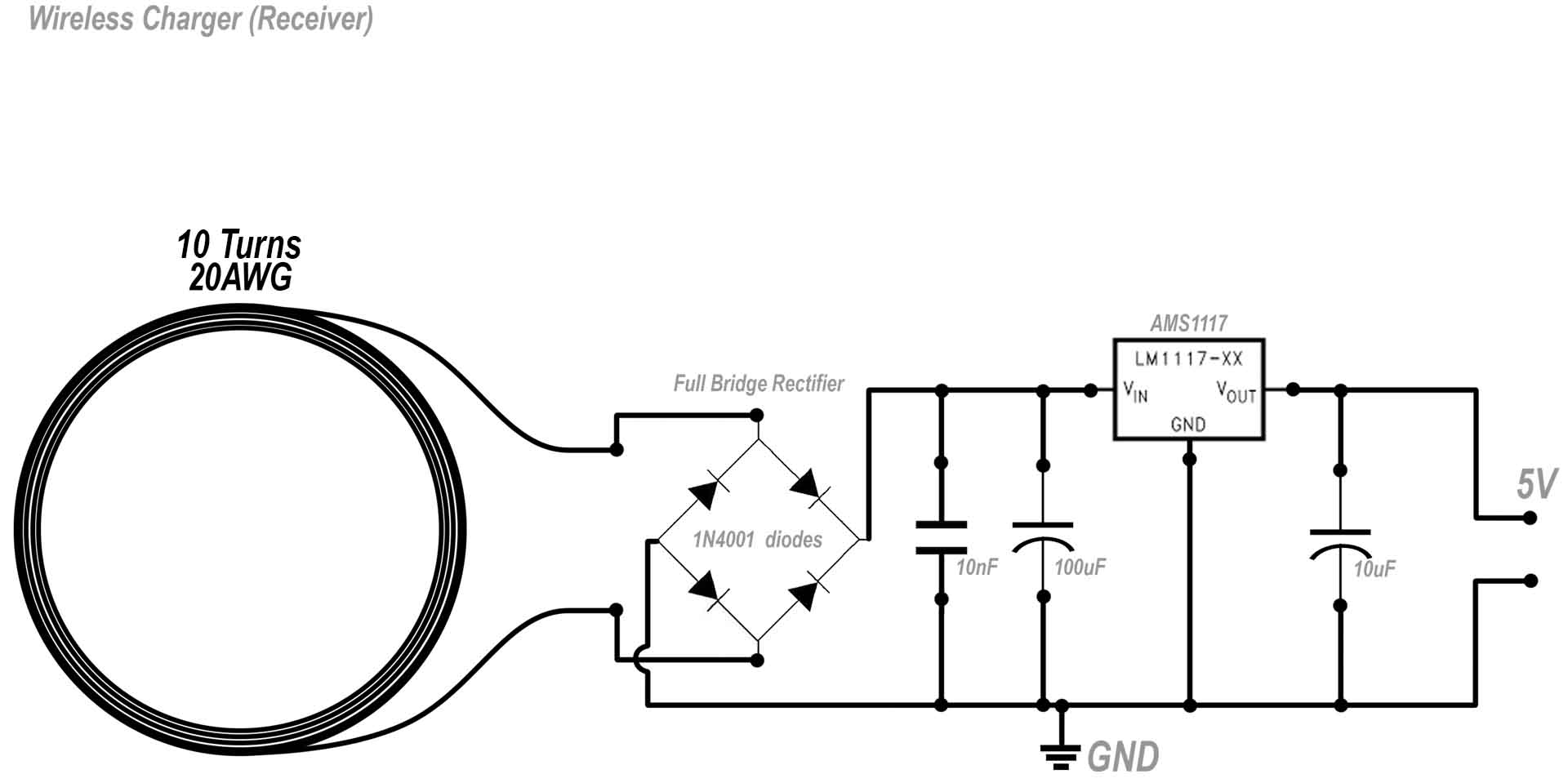
This is the circuit for the receiver. I've made the coil with 10 turns so it will output a bit higher voltage. Then, first step is to rectify the signal with the diodes bridge. We filter the spikes with those capacitors and then we regulate the output at 5V using the AMS1117 regulator or any other. We add a filter cap at the output and that's it for the receiver. Even the voltage from the receiver coil is 16V, the AMS1115 will keep the output always at maximum 5V.