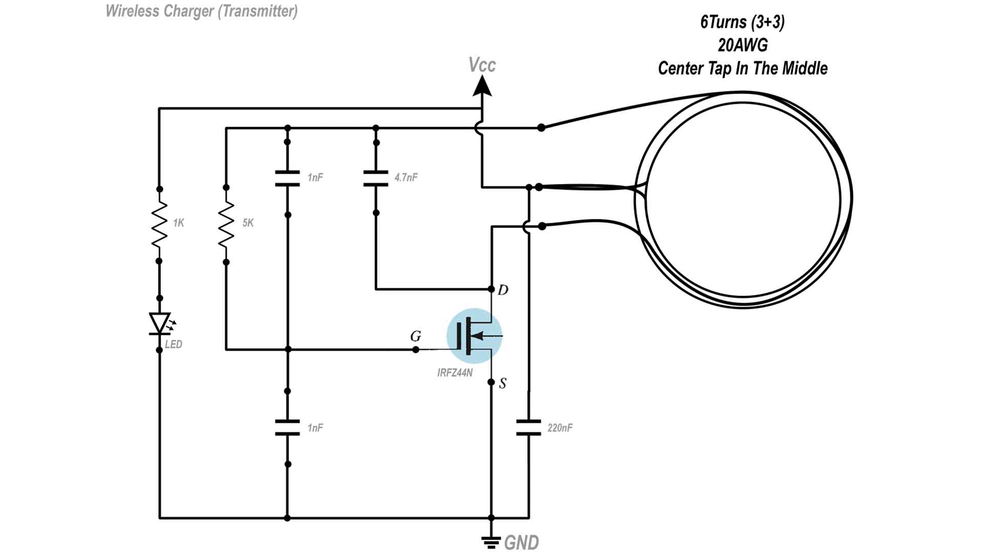
This is the circuit for the power transmitter. Depending on how you make the coil, it will affect the resonance frequency together with the 220nF capacitor that creates the LC tank. The diameter and amount of loops of the coil is important. In my case, for my tests the diameter was 8cm and I've used 6 loops with center tap in the middle, so 3 loops before the middle point and 3 more after. This circuit will automatically create the resonance frequency and even we change the load, the circuit will automatically adapt. Since the gate of the MOSFET is connected to the coil. each time the voltage oscilaltes, it will turn the transistor on and off and like that creating the oscillations. The LED is just for indication that the circuit is powered on.