Whenever we have a system with a microcontroller acting on motors, we'll definitely find voltage and current problems. The micro processors typically work at a voltage of 3.3 or 5 volts and use very low power.
by: ELECTRONOOBS on 2026-05-26
All the prices are low due to China purchase. It's up to you wait or not.
1. Two MOSFET IRF3205 transistors (pack-2: 1€) LINK eBay
2. Three TSC428CPA drivers (pack-10: 4€) LINK eBay (I've used IR2301 but this is quite expensive)
3. Three power diodes(pack-100: 1€) LINK eBay
4. One 100uF 25V capacitor (pack-20: 1€) LINK eBay
5. Ten 0,1uF 0805 size capacitor (pack-100: 1€) LINK eBay
6. Six 22uF capacitor (pack-10: 1€) LINK eBay
7. Ten 22pF capacitor (pack-100: 1€) LINK eBay
8. 0805 size resistor: 100, 1k 2k (pack-100: 1€) LINK eBay
9. 5V ams1117 voltage regulator (pack-10: 1€) LINK eBay
10. Female and male pcb pins (pack-10: 1€) LINK eBay
11. Huge 4700uF 16V capacitor (1€) LINK eBay
12. Arduino NANO (2€)
13. Wires, conectors, solder, soldering iron... (0€)
Intro!
Whenever we have a system with a microcontroller acting on motors, we'll definitely find voltage and current problems. The micro processors typically work at a voltage of 3.3 or 5 volts and use very low power. Instead motors are beasts whose main food is current. In a project that uses motors we can consume more than 20A and that amount of current won't be given by any microcontroller. Therefore we need to separate the high amp 12V part of our circuit from the low 5V part. When i say motors I refer to triple phased brushless motors. By having three-phase motors things get complicated compared with a simple DC motor. We have to power 3 inputs to the motor in a very precise sequence. To generate that sequence of high or low state of the motor inputs we will use an ESC (electronic speed control).
We can see in the animation above that we have to switch 3 inputs H1, H2 and H3 in a certain sequence. We will call the 3 inputs, input A, B and C. The sequence we need to create is as follows:
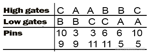
Where the high gates referes to the transistors connected to Vdd and low gate to the transistors connected to GND in our three-phase bridge that we can see below. The pins represent connections to the microcontroller.
A little bit of extra info
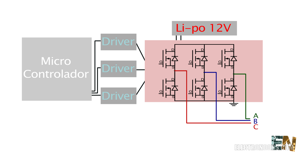
We observe the general schematic of an electronic speed controller and divide it into three parts. First of all we need a microcontroller that will make the micro-process part. The microcontroller processes the data and decide which signal has to be send to the next part, the drivers. The function of these drivers is to apply the necessary voltage at the mosfets transistors gates of the third part called three-phase bridge and open or close the flow of current through these transistors. Finally, the third section bears the name of three-phase bridge. We have to power a three-phase motor following a certain sequence and flow the current through the motor windings. Opening and closing 6 transistors in a very precise way we could achieve the desired sequence in order to rotate the motor.
As already mentioned the schematic is very general. To synchronize the rotation speed of the motor with our generated sequence at all time we need to control the motor position and compare it with the desired position. For that we measure the EMF or electromagnetic field created by the rotation of the motor, like dynamo magnets create a certain electromagnetic force in the motor windings. By measureing the voltage drop in the motor terminals we can make a fine micro-process and know the position of the motor and synchronize each turn.
To understand better the inner function of a three-phase brushless motor we look at the figure above. We know that the motor has a multiple of 3 number of coils. The coils are distributed equidistantly around The perimeter of the motor. In this way between each coil there will be 360 degrees divided by the number of coils. In our case the engine is 12 coils, 4 coils for each of the 3 inputs. In the above figure those are represented by only one coil for each input. The moving part of the motor can be external or internal shaft , in this case is external. Around the movable part we need to place some strong magnets in the same way as the 12 coils, equally spaced. We know that applying a current flow through the coils, a magnetic field is created depending of the current flow direction.
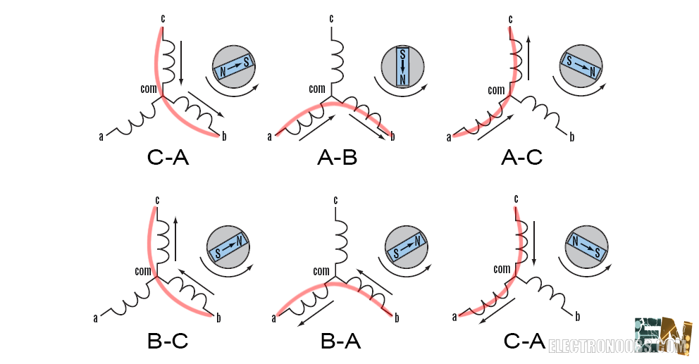
Alternating the current flow direction through the coils, we alternate the polarity of the electromagnetic field created in souch a way that we'll have opposite poles between the coils and magnets in certain points of time. Looking at the figure we can see that we start switching the upper "C" gate and the lower "A" gate. In this way we make current flow from C to A, creating a magnetic field through the two coils. That created field is opposite to the magnets field and that creates a push force which move forward the interval axis (360/12 degrees). Just at the moment when the coils pass through one each other middle, the next magnet have to switch to the next state so we have to make current flow from A to B and so forth creating an infinite loop that repeats every 6 states.
How to detect BEMF and sincronise our sequence:We know that a magnet creates a magnetic field around it. Once you put a coil in front of him, the movement change the field flow through the coil creating a current flow throug the windings. As more field flows through the coil, higher current intensity passes through the winding and a higher tension could fall on the terminals. Let's look at the next BEMF detection example:
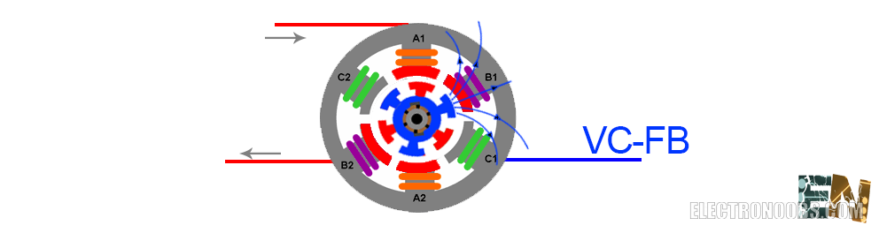
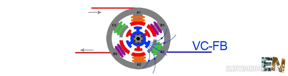
We observe in the above figure that the upper gate of the A output and the lower gate of the B are activated. That creates a curent flow from A to B coils in the direction of thee grey arrows. This current flow creates a equal magnetic field in bowth A and B coils. That magnetic field will push the oposite magnetic field of the exterior magnets rotating the motor. In this example we call the red color of the magnets south polarized and the blue ones north polarized. We obserbe blue arrows getting out of the blue magnet. Let's look at the C coil for now. Those field lines are not crossing the C coil yet. We can see that almost all the field lines are out of the coil but in the next figure, a few moments after we can see that there are a few lines crossing the coil. In this way the created current flow it is afected by the rotation of the motor. This gives us a voltage change VC-FB which we can measure with our microcontroller ADC. As the field lines are geting more perpendicular to the coil, the current flow is higher each time and so it's the voltage drop.

n the next figure we observe that the field lines are totally crossing the C coil. This means that the field flow is maximum and so is the current flow in the C coil. This is the exact moment when we need to change to the next step of our sequence. If we are able to detect this exact moment with our microcontroller we could jump to the next part of our sequence in the right moment. AS we could see, we have a voltage drop in non-activated coil which depends of the motor movement. We can measure that voltage drop using our ADC and compare it with the mean of all 3 coils voltage. When we detect that maximum voltage we could make the sequence change.
Let's start
We already know what we have to do. Mount the three-phase bridge, connect a microcontroller and read the outputs of BEMF of the motor and create a switch sequence depending on that BEMF read. First of all we create a schematic in Design Spark program. You can use any PCB design program. To make the schematic import all specified components. Make the connections and create the PCB.
Watch the next video and learn how to create a PCB in Design Spark:
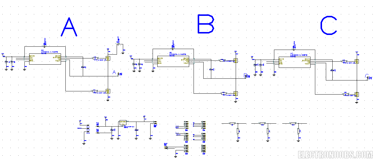
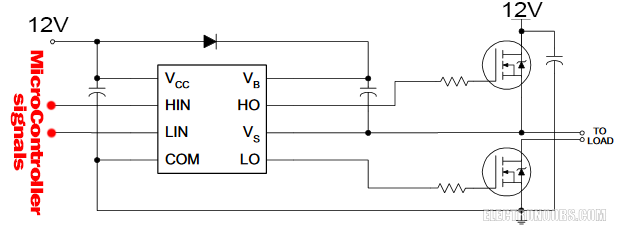
Anyway we can see 3 controllers (drivers) Dual 2, each connected to two MOSFETs. The controllers inputs are connected to the microcontroller Arduino Nano. The outputs of the three-phase bridge, each with a voltage divider with resistors 1k and 2k connected to the analog input pins of the Arduino. To make the connection of the drivers take a look at the following schematic:
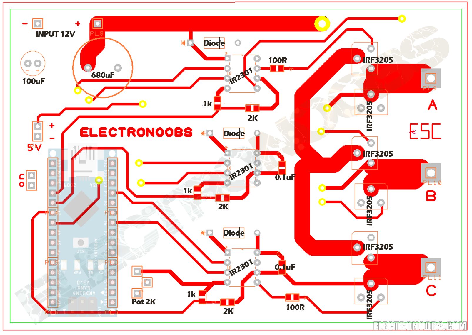
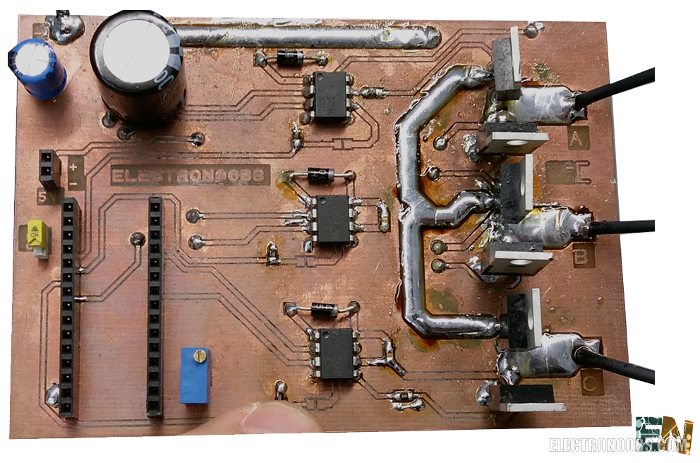
We now have the schematic. Let's create our PCB. Create a two-layer PCB and distribute all components. In the next photo we have the top layer with all the components. I've added all the values for each component. Be carreful while routing.
Now let's take a look at the bottom copper layer. We can see that the through holes are the same. On
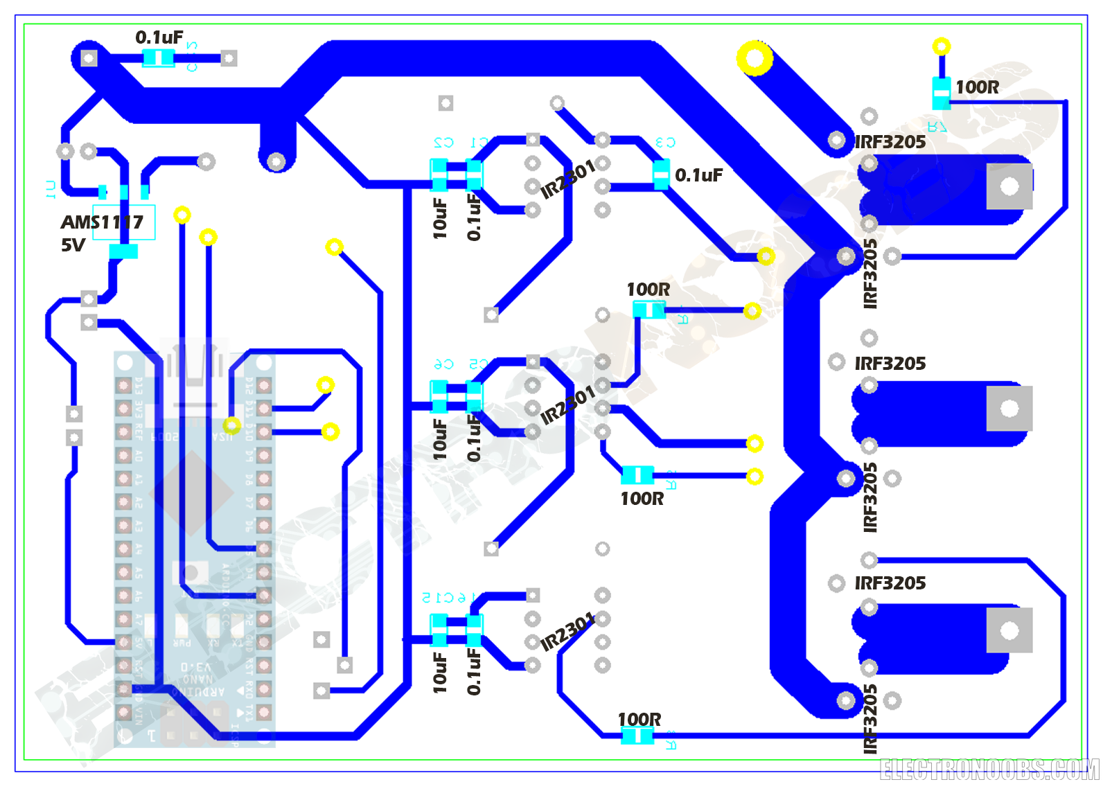
Now let's join together the two layers. I've divided them in order to be able to clearly see each connection. Follow this circuit to mount yours. Maybe print them on a sheet of A4 paper and have them in front of you while solderng.
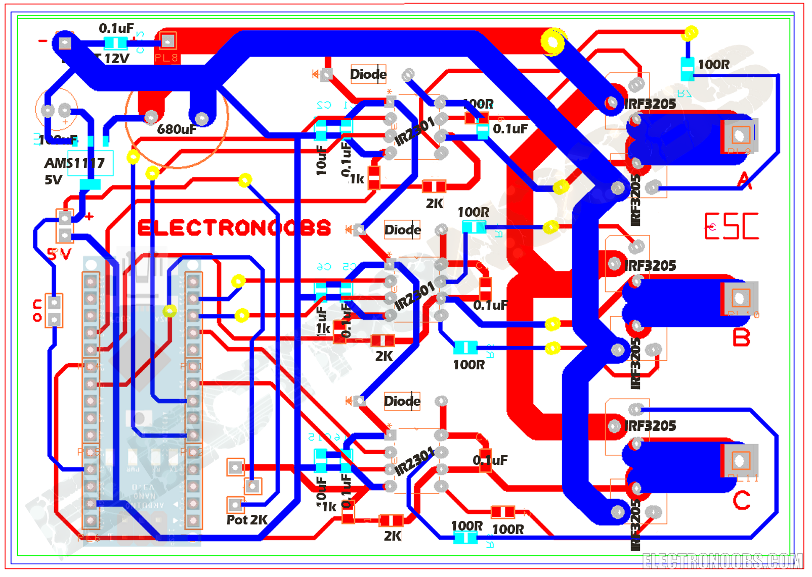
We observe the necessary pins for the Arduino to fit in, 12-24 volst input, the (drivers) and 6 MOSFETs. We also note that the main tracks are very thick, 4mm. That's because through them will flow more than 20A of current. The voltage regulator provides stable 5 volts for the arduino. Once we have the PCB, generate gerbers and send them to the CNC milling machine. Such a machine will create a milled double PCB. After (milling) our board looks like this:
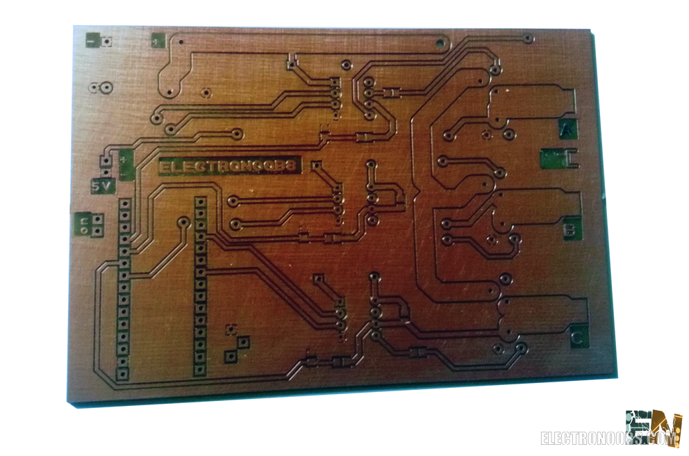
We started welding the components one by one. We fill the main tracks with a lot of solder to give them more resistance front a high current.
We have finished our PCB. We connect our Arduino in place and move on to the code part. First we will run a code without detection of the BEMF where simply varying the potentiometer we will vary the motor speed. Without detecting EMF and without the algorithm the motor could stop in every moment and you could notice that it has a very low torque.?
We can see that in the code we are not using "delays" because any delay will affect the entire sequence of rotation. We have 6 variables for the states of each transistor of the three-phase bridge. 6 cases will be created to complete a sequence. Then change time between each sequence is given by the analog input from the potentiometer value.
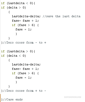
Upload the code with EMF detection. If we look at the code we see that we need to select the analog pins that will measure the voltage at each terminal, in my case are the pins A2, A3 and A4. The pins that activate the transistors are the same. For the phase change two deltas are created. A current delta and an previous one because we have a phase change depending on the detection of "virtual zero" that can be down from positive to negative or vice versa , up from negative to positive voltages, so thats why we need two deltas . In the Setup we define the pins functionality. In the first loop we measure the voltage on each analog input and make the sum of the 3 measures. This sum will be our "virtual zero" representing the common point of intersection of the three voltages. The delay will be made in the same manner as in the case without emf, by measureing the transcuren microseconds and changing the value of a potentiometer. But the phase shift will come affected by delta values this time. The delta is calculated at each stage and at the end of the code we compare the deltas to detect when we pass through the "virtual zero". It is that the exact time when we should change the phase.
Comments


Leave a comment
Please login in order to comment.