Some time back I've bought this magnetic levitation kit from eBay in order to take a look on how it works and what we need to make it. I'm planning to make my own levitation circuit using Arduino, but that's for a future project. The kit I've received had no manual or circuit so i had to make some reversed engineering in order to get the scheamtic. But all the values for each component are labeled on to the PCB so is easy to mount it. In this tutorial you will have the GERBER files for the PCB, the scheamtic and all the parts you need for this if you want to make your own. So let's see...
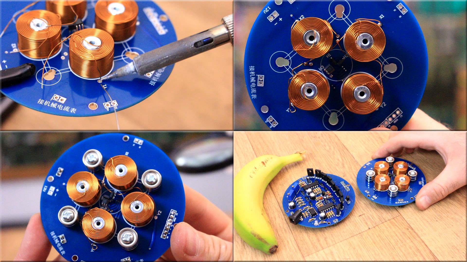
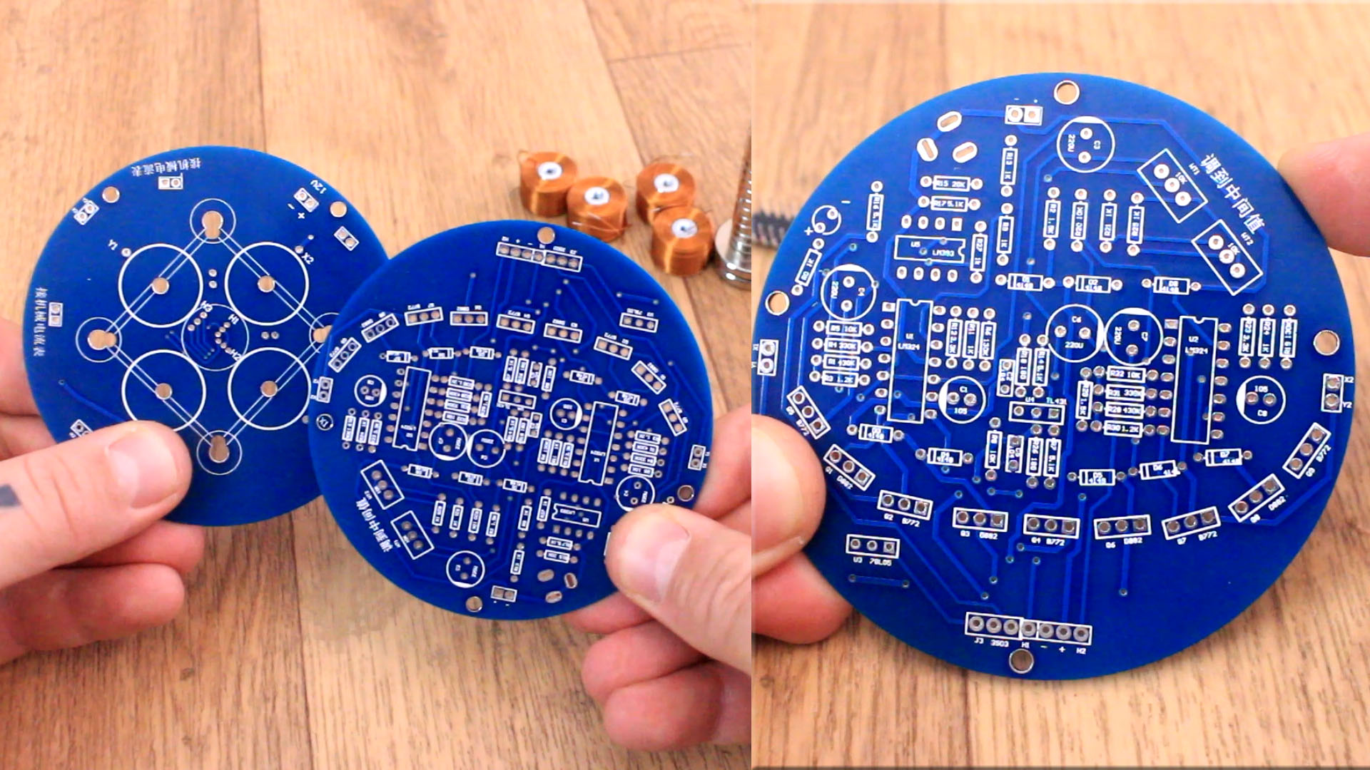
When you receive this kit you will get 2 PCBs, 4 coils and 12 small neodymium magnets, 1 big magnet and a lot of plastic bags with all of the components. Each bag has labels and on the PCBs we have the silklayer with the name and value of each component so mounting this is just follow the components. So you have to check the value on the PCB, search that component in the bags and solder that. We need 2 PCBs because on one we will have the components and on the other we have the coils and magnets that will keep the big magnet in the air.
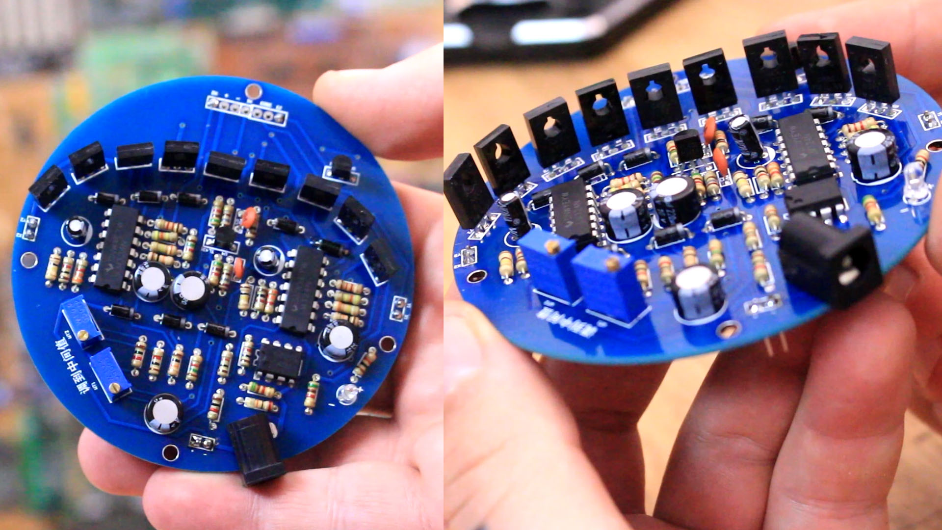
Before we sodler the parts, have in mind that there are some components that have no mark of which is the front side but have in mind that usually the squared pad represents the first pin of that component. So, just look at the pad, check the component online to see which is the first pin and then solder that. SO, I first solder the two LM234 OPAMPs.
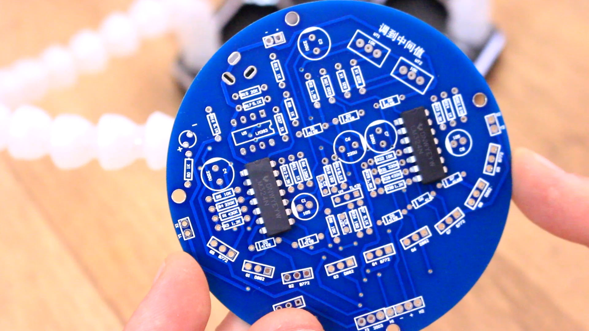
So we have soldered those two LM324 amplifiers. Then I solder the small amplifier as well, the LM393. After that I solder the voltage refference and voltage regulators 78L05ML and the TL431 refference. For these two components look at the squared pad for the first pin and make sure you don't solder it backwards. Now I can start soldering all the resistors. These are all trough-hole. Just look at the value marked on to the PCB, search that resistor in the plastic bags and place that on the PCB. Then I flip the board and solder all resistors.
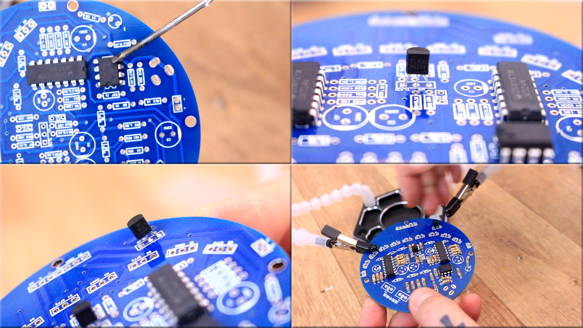
After I add the resistors I can place the capacitors. Becareful with the polarized caps and not put those backwards. We also have 2 non-polarized capacitors 100nF. Then we can add all the diodes including that small LED. We add te two potentiometers, the DC connector and finally we add the BJT transistors. We have a total of 9 transistors. We add the small male pins and the PCB is ready. All the components are palced on the top side of the PCB except the male pins. These male pins will be used to connect this PCB with the bottom PCB.
Now that we have the bottom PCB, we start with the second board. Now is very important to palce the hall sensors in the correct position. But first, for that, we need to place the coils. So add the screw on the bottom side and the screw in place each coil with the wires on the top side. We have one end of the wire in the middle of the coil and one on the side of the coil. Once we haev the coils palced we can add the hall sensors because now we know the height of the coils and that's important.
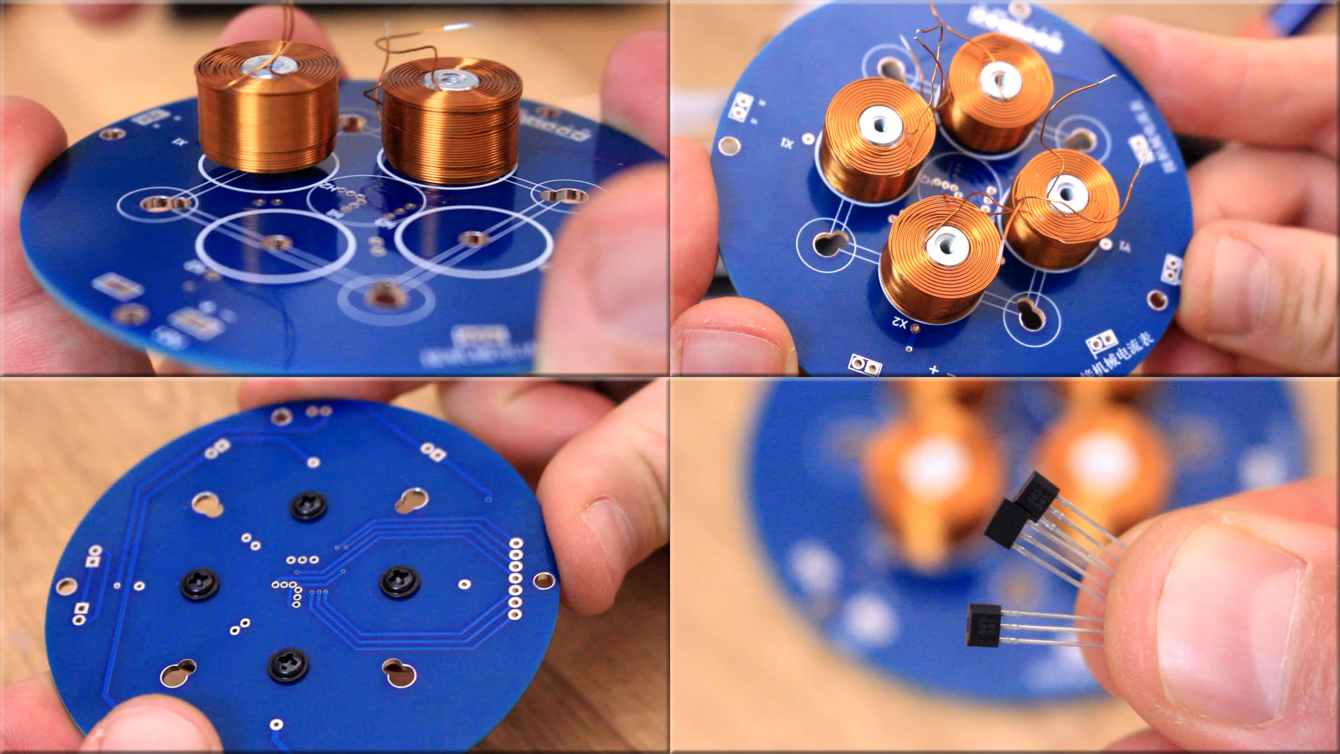
Ok, now we have to bend one hall sensor 90 degrees wiht the front part facing upwards. Then we solder that on the H3 pads at the height of the coils as you can see in the pictures. Then we solder the other two hall sensors with 90 degrees in beterrn one each other and at the height of the middle of the coils more or less. See the pictures for more details. And taht's it. Not we can solder the wires from the coils.
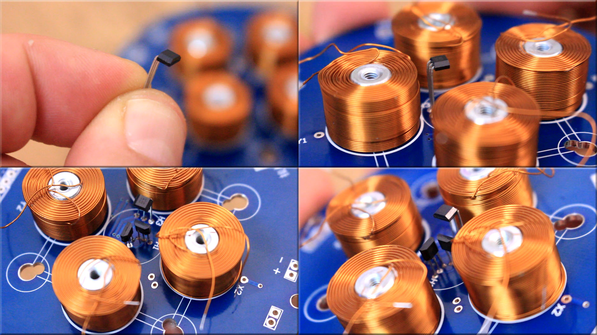
Now you have to solder the wires from the coils. The wire that is coming out from the middle of the coil will go to the X or Y pad. Have in mind we have to connect X1 with Y1 and X2 with Y2. Then solder the wires from the side of the coils to the other two pads and make the connections. Finally we add the magnets, 3 for each pack using the given screws and the board is ready. Both boards are ready.