 About me
  History
  Let's learn
  Contact us
  Arduino tutorials
 Circuits tutorials
  Robotics tutorials
 Q&A
Q&A Blog
Blog  Arduino
  Circuits
 Robotics
  Modules
  Gadgets
  Printers
  Materials
  3D objects
  3D edit
  Donate
  Reviews
  Advertising


DIY 3bit flash ADC
0.0 Basic intro
What’s up my friends, welcome back. This will be a very short tutorial on analog to digital converters or better known as ADCs. Any circuit that needs to process signals coming from the exterior world will need and ADC in order to pass analog electric signals to a digital representation.
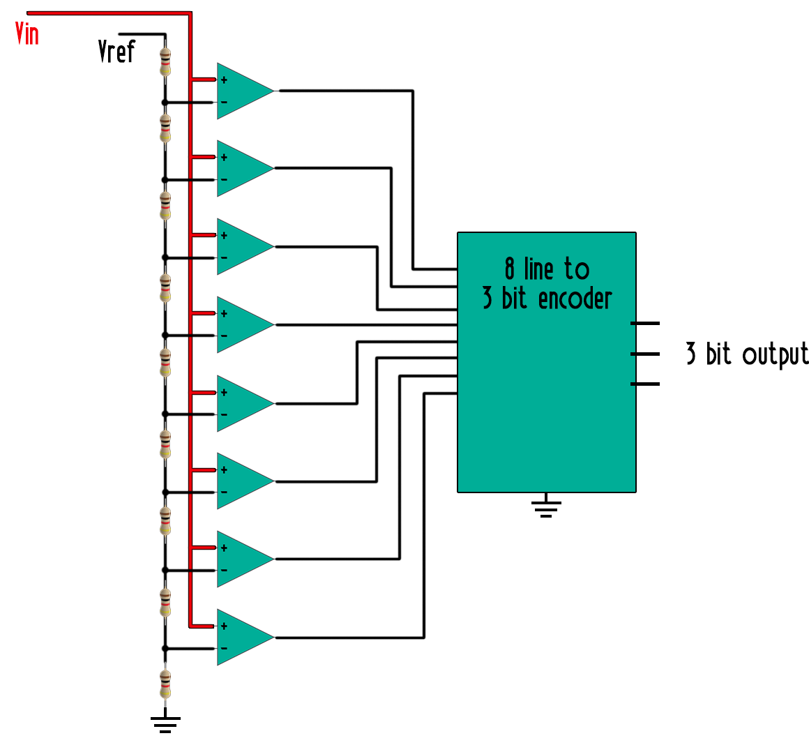
So today we will take a brief lesson on ADC, how they work, how to define their performance, types of ADCs and final build our crude 3-bit ADC like this one.
So, let’s get started.

1.0 What do we need?
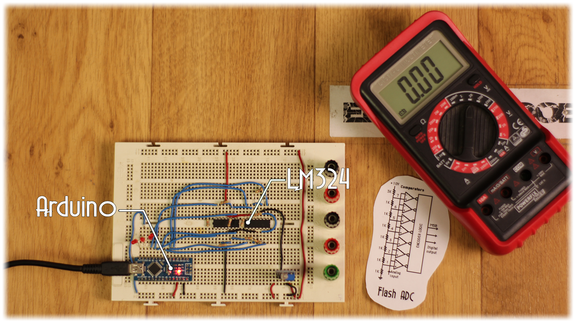
I will talk a bit about all the components. You ahve a photo below with some of the components. For more details go to the page of the full part list. There you will find all the components, prices and different options.
See the full part list here:
2.1 Flash ADC blocks
The most basic types of ADCs are the FLASH, priority encoder, pipeline ADC and successive approximation register or SAR. Later in this tutorial we will see how to create a crude flash type ADC with some OPAMPs. Since in this project we won’t talk about AC signals that much since we will work with very low frequencies. All I want is to read an analog value of for example the output of a light sensor. If the light is always the same, the output voltage won’t change so basically in this example the frequency is zero and we are talking about DC input. Also, the rate that the light will change is very slow.
Let’s now imagine that my Arduino has no ADC, only digital inputs which could detect a low or high value.
How can I measure the voltage of the light light sensor? Let’s take a look on this very basic flash ADC above. We basically have an array of operational amplifiers, a bunch of voltage dividers and an encoder. I’ll explain how each of these components work.
2.2 The voltage divider
First let’s look at the voltage divider. It is made out of two resistors. We name those R1 and R2. I guess that we are all familiar with the ohm law which says that the voltage drop across a resistor is equal to the current that passes through that resistor multiplied by the resistance value.
So, let’s imagine that we apply a voltage Vin at the input here on R1 and let’s name the voltage in the middle of these two resistors Vout. Using the ohm law, the current that pases through R1 is the voltage drop divided by its resistance. So the current is Vout minus Vin divided by R1.
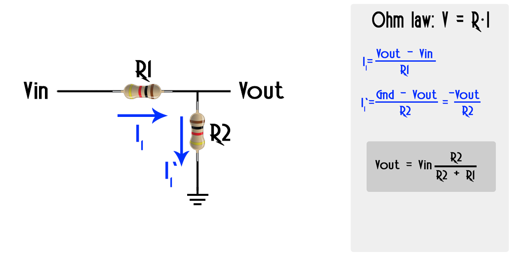
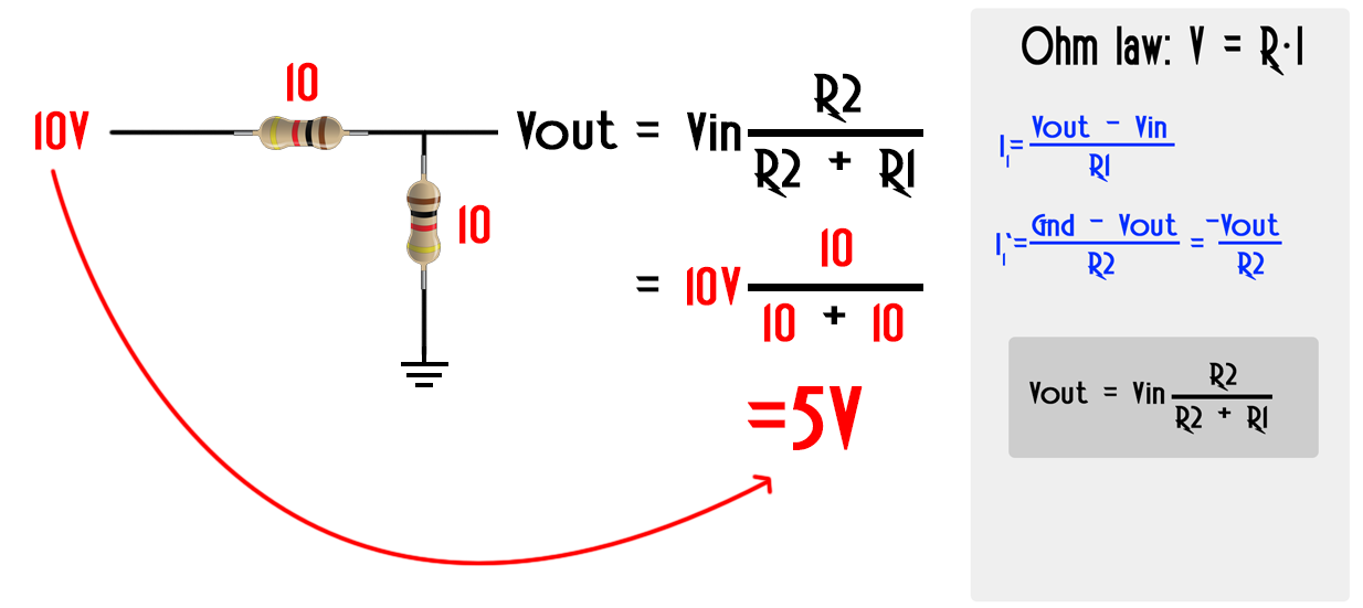
But that same current will now pass through R2 since is the only way to go. So now in this case, that same current is ground minus Vout divided by R2. So now we have two equations for the same current value. If we rearrange these values we get that Vout is the input multiplied by R2 divided by the sum of R1 and R2. And there we have our voltage divider. Let’s give some values. If we apply 10 volts at the input and both resistors are 10 ohms, we get an output of 5 volts. So, we have divided by half the input. Pretty basic, right?
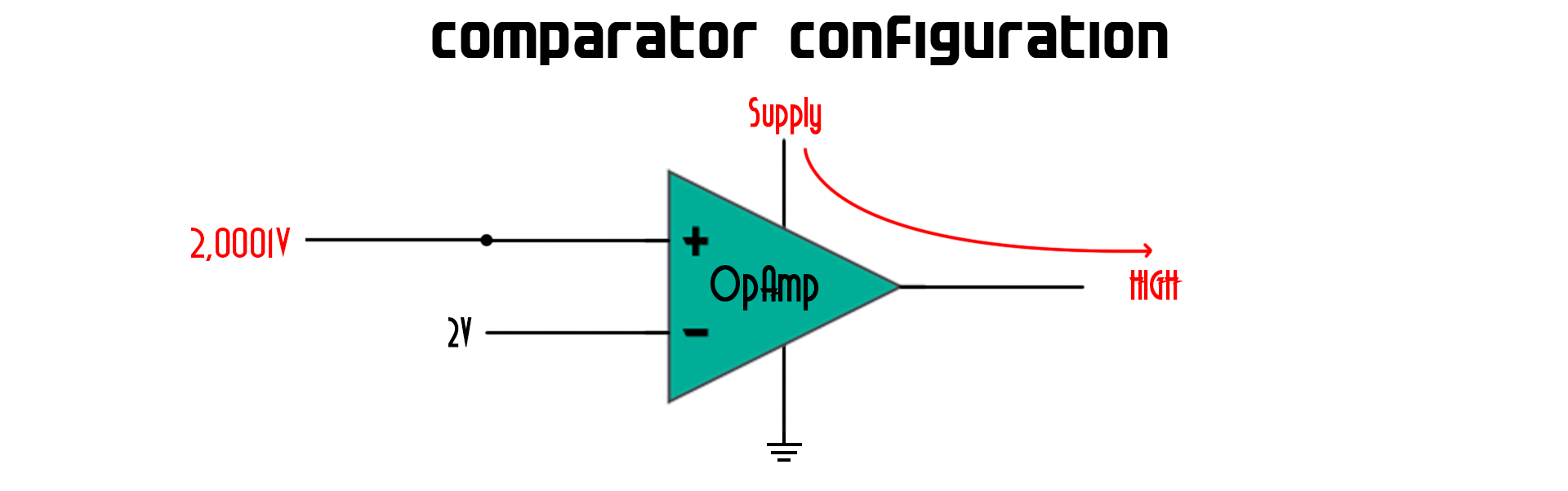
2.3 OpAmp comparator
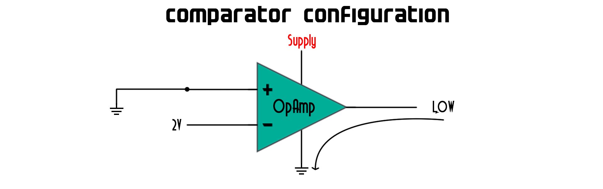
Now let’s talk about OPAMs. The photo below has the icon of an amplifier. We have a positive input and a negative input. Then we have the output and the supply of the OPAMP. The gain of an amplifier in comparator configuration is basically infinite. So exactly in the moment when the positive input is higher than the negative one, we will have a high output with a value in this case of the supply voltage.
So, for example if the negative input is connected to 2 volts and the positive to ground we have a low output. I start increasing the voltage at the positive input from 0 and exactly when I reach a bit more than 2 volts the output is high.
That’s why it is called comparator, it compares which one is higher. The last element is an encoder, which in our case will be the Arduino. It will read the inputs and give a binary output. So now that we know this let’s take a look at the schematic of the flash ADC, in this case of 3 bits. .