The buck–boost converter is a type of DC-to-DC converter that has an output voltage magnitude that is either greater than or less than the input voltage magnitude. It is equivalent to a flyback converter using a single inductor instead of a transformer.
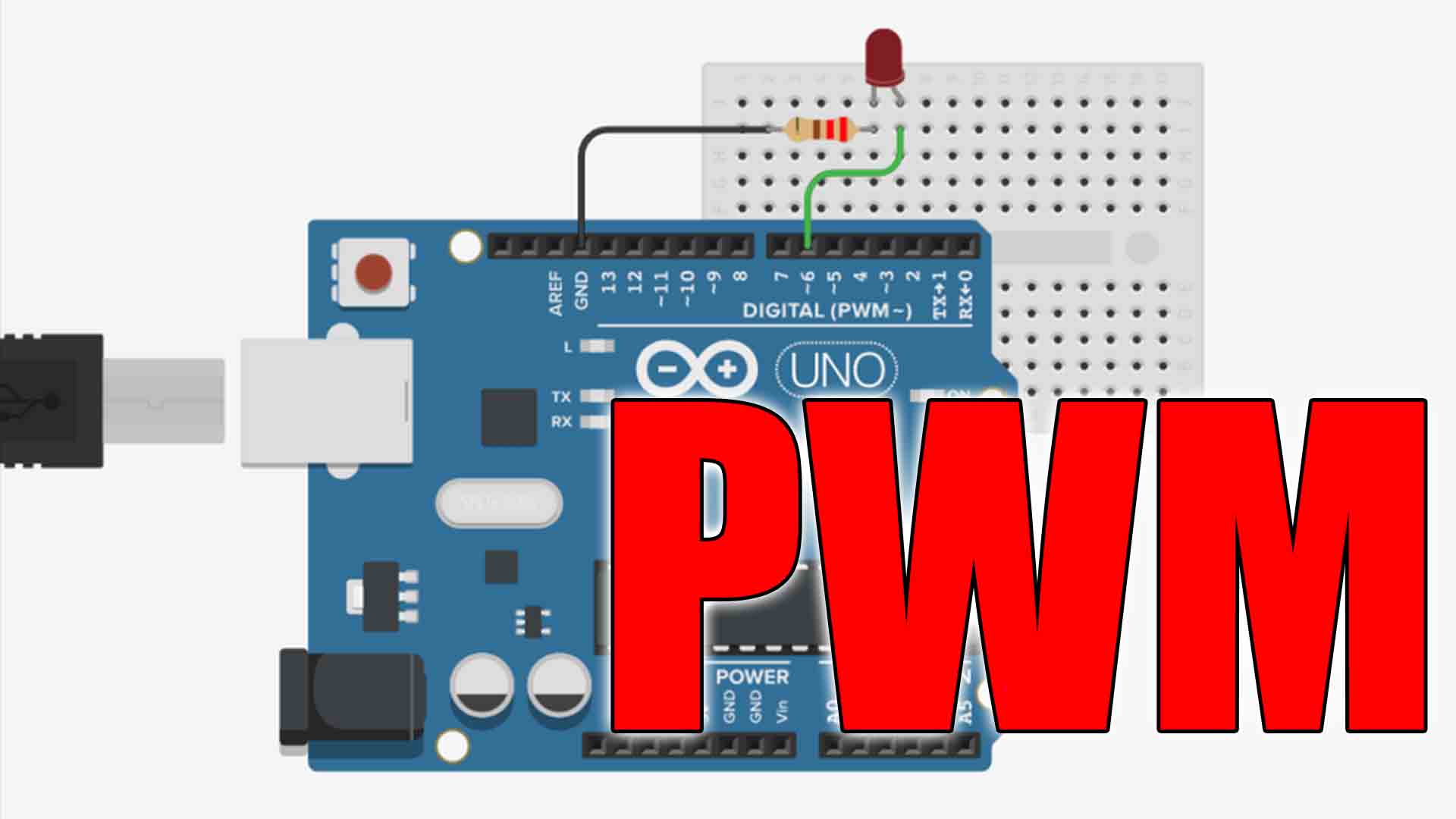
In this tutorial we will learn how to build and how a DC to DC buck-boost converter works. The circuit is very basic using just one diode, an inductor and a capacitor. The switch will be a MOSFET transistor and to create the PWM signal we will use a 555 timer in the PWM configuration, boost adjustable controller or one Arduino NANO. But first let's study a little bit of theory. We have the buck-boost converter circuit in the next figure where we can see the switch, inductor and capacitor and of course we add a load to the output.

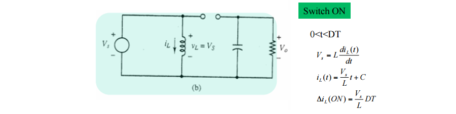
Like the buck and boost converters, the operation of the buck-boost is best understood in terms of the inductor's "reluctance" to allow rapid change in current. From the initial state in which nothing is charged and the switch is open, the current through the inductor is zero. When the switch is first closed, the blocking diode prevents current from flowing into the right hand side of the circuit, so it must all flow through the inductor. However, since the inductor doesn't like rapid current change, it will initially keep the current low by dropping most of the voltage provided by the source. Over time, the inductor will allow the current to slowly increase by decreasing its voltage drop. Also during this time, the inductor will store energy in the form of a magnetic field. We have the switch closed so in this case we obtain the current through the inductor using the next formulas.
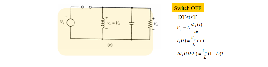
When the switch is opened, current will be reduced as the impedance is higher. The magnetic field previously created will be destroyed to maintain the current towards the load. In this case the voltage across the inductor is the output voltage. So once again using the next figure formulas we obtain the current of the OFF part depending on the duty cycle.
Ok, now if we want to obtain the output depending on the input and the duty cycle of the PWM all we have to do is to make the sum of the On and Off current equal to 0. That means that the On current is equal to the Off current. So that will give us:
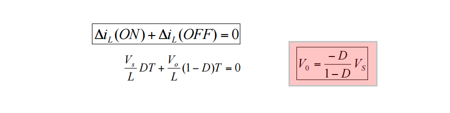
So we've obtain that the output is depending of the duty cycle disproportionate and also proportional. The duty cycle of the PWM can have values between 0 and 1. In this way we could achive both higher and lower voltages than the onput. That's why this configuration is called step down-up converter.
This 555 configuration will create a PWM signal and apply that signal to the MOSFET gate. The circuit works ok but it has a big problem. The output will change if we change the output load because the circuit has no feedback. Ok so we will use the next schematic for our buck-boost converter example. To create the PWM signal we will use the 555 timer with the PWM configuration. With the P1 potentiometer we can change the duty cycle of the PWM signal, and at the same time the output value. For the MOSFET you could use the PMOS IRF4905. You could always try different inductance values for the inductor and see the results.
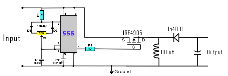
The input could be up yo 15 volts. Don't apply higher voltage or you could burn the 555 timer. Connect the PWM (pin 3 of the 555 timer) to the MOSFET (switch) gate. Add an output load and test the circuit. You could obtain output values higher than the input.
Sincerely, this circuit has no sense but to learn. The Arduino NANO already has a 5V linear voltage regulator that will lower the efficiency of the circuit. So the main goal is to learn how the circuit, the feedback and the PWM signal work in order to achive the desired output.
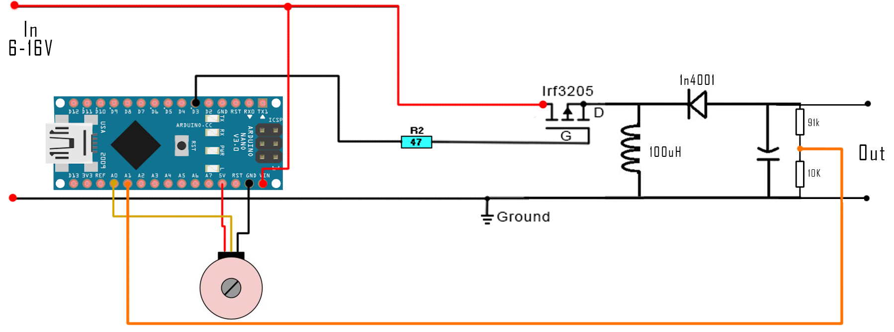
AAs you can see we have a potentiometer connected to the analog input A0. With this potentiometer we will choose the output value between 1 and 50 volts aprox (your output values may vary). At the output of the circuit we have a voltage divider that will lower the voltage from maximum 50V to under 5 volts because that's the maximum input voltage of the Arduino ADCs. In the code we compare this two voltages and increase or decrease the PWM width in order to keep the output constant. Just copy and upload the next code to the Arduino for this example.
//https://www.youtube.com/c/ELECTRONOOBS
//SUBSCRIBE, Thank you!
int potentiometer = A0;
int feedback = A1;
int PWM = 3;
int pwm = 0;

void setup() {
  pinMode(potentiometer, INPUT);
  pinMode(feedback, INPUT);
  pinMode(PWM, OUTPUT);
}

void loop() {
  float voltage = analogRead(potentiometer);
  float output  = analogRead(feedback);

  if (voltage > output)
   {
    pwm = pwm+1;
    pwm = constrain(pwm, 0, 255);
   }

  if (voltage < output)
   {
    pwm = pwm-1;
    pwm = constrain(pwm, 0, 255);
   }

   analogWrite(PWM,pwm);
}
If my videos help you, consider supporting my work on my PATREON or a donation on my PayPal. Thanks again and see you later guys.