A H-bridge is an electronic circuit that switches the polarity of a voltage applied to a load. These circuits are often used in robotics and other applications to allow DC motors to run forwards or backwards.[1] The name is derived from its common schematic diagram representation, with four switching elements configured as the branches of a letter "H" and the load connected as the cross-bar.
Most DC-to-AC converters (power inverters), most AC/AC converters, the DC-to-DC push–pull converter, isolated DC-to-DC converter[2] most motor controllers, and many other kinds of power electronics use H bridges. In particular, a bipolar stepper motor is almost always driven by a motor controller containing two H bridges.
1.
2.
3.
4.
5.
6.
7.
8.
Whenever you want to control a DC motor you'll have tension problems between your microcontroller and your motors. Most of the microcontrollers operate at 5 volts and have very low current outputs. If we really want to use a motor with a voltage of 12 V and current up to 4 amps need something between the two sides. An H bridge, named for its H-shaped configuration is exactly what we need. An H-bridge is a configuration of 4 activated doors with small signals in pairs of two. Current will flow in the one direction or another depending of the switched "doors".
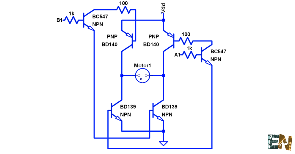
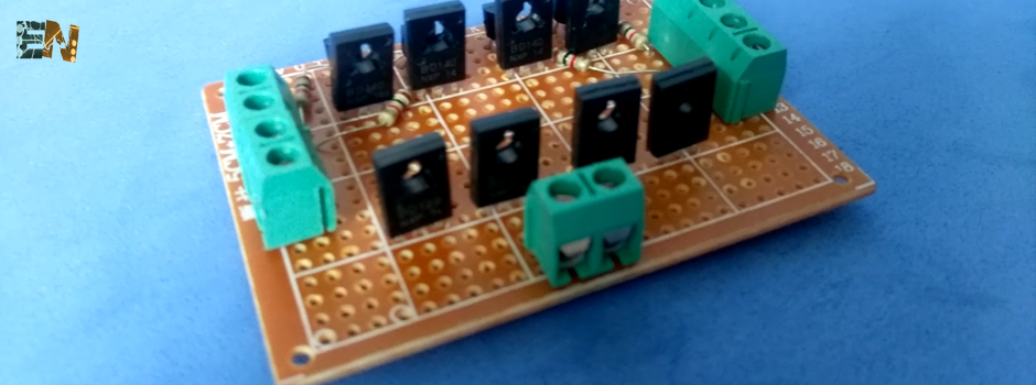
2 PNP transistors are connected on the top of the 5x7cm PCB with equal distances from each other. Welded and cut left over wires. 2 BD139 NPN transistors are placed at the bottom of the board. Welde them like previous. 2 BC547 transistors are connected near the BD140 to make connection easier. Connect them through 2 resistors of 100 ohms each. All the connectors are placed and connected with two 1k ohm resistors to the two BC547 transistors bases. Wiring begins with thin wires. First GND is connected to the emitters of the transistors BD139. After, Vdd is connected to the emitters of the BD140 transisotres. Outputs to the board pins are connected and we are ready. To test the circuit I've made a small Arduino code to control rotation direction and speed with PWM signals
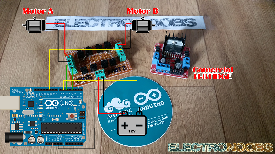
Connect the pins to the H-bridge module, upload the code to the arduino and see the results.
If my videos help you, consider supporting my work on my PATREON or a donation on my PayPal. Thanks again and see you later guys.